KJ-01.02.Instruction Manual.REV.02.pdf - 第126页
5 − 30 (8) Layer T he def ault sett ing is “Layer 2”. Layer is used to designate t he order of component placement. Normally , a chip mounter m ay place a QFP chip on a board prior t o a chip component even though you wa…
5 − 29
(4) Component name
Enter the component name using the formula bar. The area for Component
data, which is described later, is allocated with the name you specified here
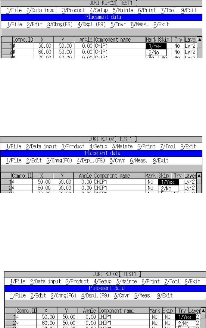
(5) Mark
Select from the pop-up menu whether or not correction is made for placement
position using the fiducial mark.
For part ID input, “NO” (this means “not used”) appears as default for the mark.
To change the default setting, using the Edit key (F2), open the pop-up menu to
select the desired item.
Figure 5.4.2.2 “Mark” pop-up menu
(6) Skip
Specify whether the machine should skip this component placement point during
production on the displayed pop-up menu, Yes or No.
“No” (for “Not skipped”) is displayed as a default in the “Skip” field. To change the
setting of the “Skip” field, press the Edit key (F2) to open the pop-up menu and
select “1/Yes” or “2/No”.
Figure 5.4.2.3 Placement data, skip pop-up menu
(7) Try
Specify whether the machine should place a component on this position as trial
operation on the displayed pop-up menu, Yes or No.
“No” (for “Not to carry out a test run”) is displayed as a default in the “Test run”
field. To change the setting of the “Try” field, press the Edit key (F2) to call a
pop-up menu and select “1/Yes” or “No”.
Figure 5.4.2.4 Placement data, trial run pop-up menu
5 − 30
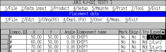
(8) Layer
The default setting is “Layer 2”.
Layer is used to designate the order of component placement. Normally, a chip
mounter may place a QFP chip on a board prior to a chip component even
though you want to place a chip component under a large QFP. To place
components one over another in the desired order, designate the layers. When
multiple layers are designated for the placement data, optimization is started
independently from the lower layer (small number) to the higher one. For the
example here, designate the chip component which is to be placed under the
QFP to layer 3 so that the chip component is surely placed under the QFP.
To change the setting, open the dialog box with the Edit key (F2) and make an
alternative choice.
Figure 5.4.2.5 Layer pop-up menu
Note: After you change the layer setting, select the [9/Nozzle sort] command
on the [2/Edit] menu. Otherwise, the component placement order will
not be changed.
See (9) “Nozzle sort” described under Section 5.4.3 for the details of this
command.
(9) Mark 1X, Mark 1Y, Mark2X, Mark2Y (Mark positions)
Using the formula bar, enter the mark position.
For a single-plane PWB, enter the coordinates viewed from the home position of
a PWB. For any other type of PWBs, enter the coordinates viewed form the
home position of a circuit.
Unless you set “YES” to the “Mark” column, your entering data of “Mark1X”,
“Mark1Y”, “Mark2X” and “Mark2Y” are not loaded to the machine. You can
teach these coordinates also.
See Section 6.2 “Teaching Coordinates” for details.
(10) Mark1T1, Mark2T1
These columns show whether the mark recognition parameter is already
obtained or not.
Move the cursor to these fields, and press the <Camera> key of the HOD to
teach the mark recognition parameter.
When the machine finishes teaching the parameter, the machine displays “OK”
on the screen. Otherwise, the machine does not display anything.
See Section 6.3 “Teaching Recognition” for details.
5 − 31
5.4.3 Menu commands
The menu commands that can be called on the Placement data editing screen are
shown below.
Table 5.4.3.1 Menu commands displayed on the Placement data screen.
1/File
2/Edit 3/Chng 4/Dspl 5/Cnvr 6/Meas. 9/Exit
1/Open...
2/Save
3/New...
4/Save as...
9/Exit
○
○
○
○
○
1/Copy 2/Delete
3/Move
4/Insert
5/Duplicate
6/Jump
7/Find
8/Vision copy
9/Nozzle sort
A/Component name
B/Pick point recalc
C/Mark database
×
△
×
×
×
△
△
×
×
×
○
1/PWB data
2/Placement data
3/Component data
4/Pickup data
5/Vision data
6/Data compl. state
×
△
△
△
○
1/Component form
2/Component list
3/Pick input
4/Feeder order
5/ Vision List
6/ Vision Form
×
×
×
×
×
×
1/PWB load
2/PWB eject
3/BOC align
○
○
○
1/Single
measurement
× 9/Exit ○
○: Available △: Available dependent on conditions ×: Unavailable
(1) File menu
You can select all of the commands displayed on the “File” menu. See Section
5.1 “File Operation Procedure” for details.
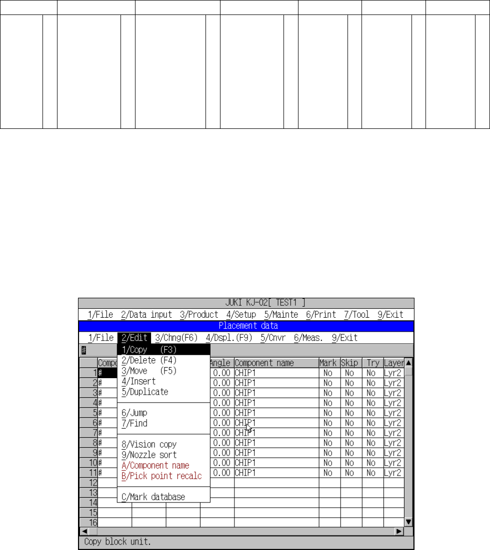
(2) Edit menu
A screen as shown in Figure 5.4.3.1 appears when [2/ Edit] is selected.
Figure 5.4.3.1 [2/ Edit] commands