KJ-01.02.Instruction Manual.REV.02.pdf - 第296页
8 − 29 8.2.3.1 Basic operation to di splay production management informati on ① Invo cation T o call the production inf orm ation box, select [3/ Conversion data] in the PW B production menu, then [2/ M anagement inf o.]…
8 − 28
8.2.3 Production management information
In the Continuous and Trial run mode, production management information is stored.
This section explains procedures to display the production management information
that has been stored.
(1) Conditions to create the production management information data
① When the production mode is set for the PWB production and the production
is performed for all placement positions (except when the placement step is
changed).
② Once the production data is created, new data for the next production is
added to the previous data.
If entirely new data is to be created, it is necessary to reset the data
creation.
(2) Items
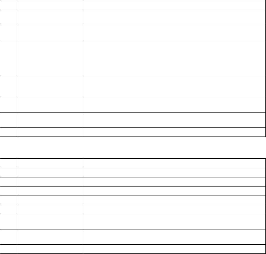
① Total management information
No. Item Description
1 Production PWB number The number of boards produced after production management information
is cleared. (Only for complete boards)
2 Production start time Date and time when the first production is started after after production
management information is cleared.
3 Running time The time duration from when production is started to when the production is
completed excluding any stop time duration. Pause time duration is also
excluded.
Production start time means when the first component is to be picked up.
Production end time means when the last component is placed.
4 Stop time The time duration from when production is started to when the production is
completed including any stop time duration when the production is put in to
halt, emergency stop, etc.
5 Picked component
number
This means the number of successfully picked components.
6 Placed component
number
This means the number of successfully placed components.
7 Detection of No. Bad mark This means the number of circuits whose bad mark is detected.
② Management information on production with the front side, rear side or tray holder
No. Item Description
1 Picked The number of components successfully picked from the feeder.
2 Placed The number of components successfully picked, then placed from the feeder.
3 PickEr.(Pickup error) The number of pickup errors occurred at the feeder.
4 Retry The number of retry over error occurred to the feeder.
5 Recog. (Recognition) Number of laser/VCS recognition retry over errors that occurred at the feeder
6 C Display the centering method: L indicates laser recognition, and V
indicates VCS recognition
7 Chip Number of components that were picked up from the feeder, detected a
tombstone error and discarded.
8 Vlfy (Verify) Unused.
8 − 29
8.2.3.1 Basic operation to display production management information
①Invocation
To call the production information box, select [3/ Conversion data] in the PWB
production menu, then [2/ Management info.].
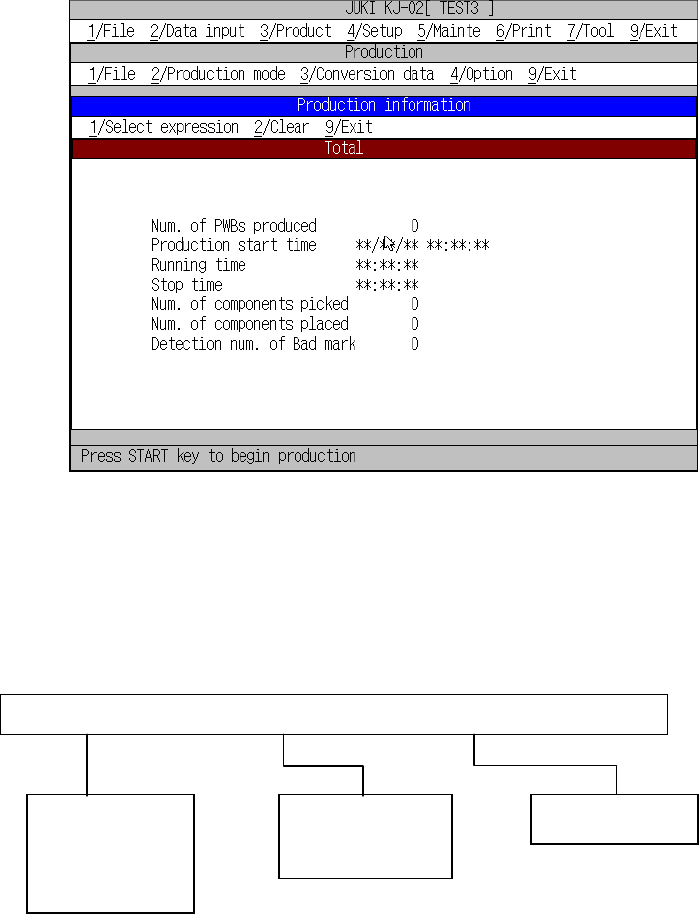
Figure 8.2.3.1 shows the Production information box.
Figure 8.2.3.1 Production information box
8.2.3.2 Commands
The figure below shows local commands available with the Production management
information box.
1/Select expression 2/Clear 9/Exit
1/Front
2/Rear
3/Tray holder
1/Clear
3/Reflesh
9/Exit
8 − 30
(1) Select expression
This command changes Production information screens.
① [1/ Total]
The overview information box is initially displayed when the Production
information screen is called.
Figure 8.2.3.1 shows the Production information box.
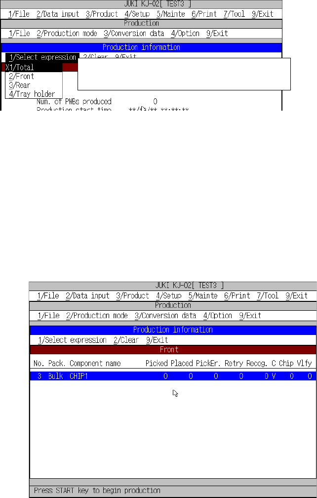
② [2/ Front]
This command displays the production management information on a tape
feeder, stick feeder or bulk feeder installed on the front side of the machine.
The screen displayed when you select this command is shown in Figure
8.2.3.2.
Figure 8.2.3.2 Production information box (for selection of [2/ Front])
Go to the desired page for reference by operating the ”(UP), ”(DOWN),
SCROLL, PAGE-UP, and PAGE-DOWN keys.]
←X indicates that this production information is
currently displayed on the screen.