KJ-01.02.Instruction Manual.REV.02.pdf - 第173页
5 − 77 (2) Display it ems No. Item Description 1 Component name Displays the component name list. 2 Pack. Displays the packaging style list. 3 Ctrg D isplays the centering method list. 4 Nzl. Displays the available noz z…
5 − 76
<3> Chng (Change) menu (F6)
The operation is the same as that for the PWB data.
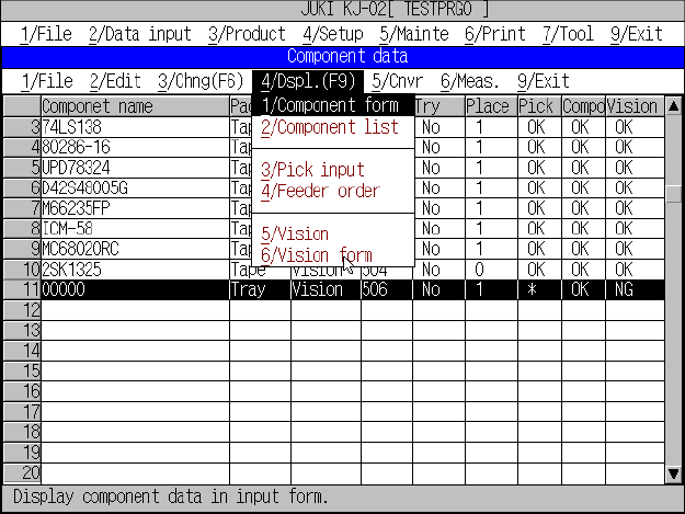
<4> Dspl. (Display) menu
This command is used to change the order of display of the component data
from form to list format and vice versa.
In the list display, only the contents of data can be referred and no data can be
edited.
Figure 5.5.2.5 Component data list screen
(1) Operation
When the display is changed from form to list, the data shown in the form
display will be located at the center of the list display.
The list data scrolls upward or downward with the up and down cursor keys.
The screen scrolls up and down when the cursor is on the top and bottom
line, respectively.
The display changes to “form” showing the line at the cursor when the
ENTER key is pressed.
5 − 77
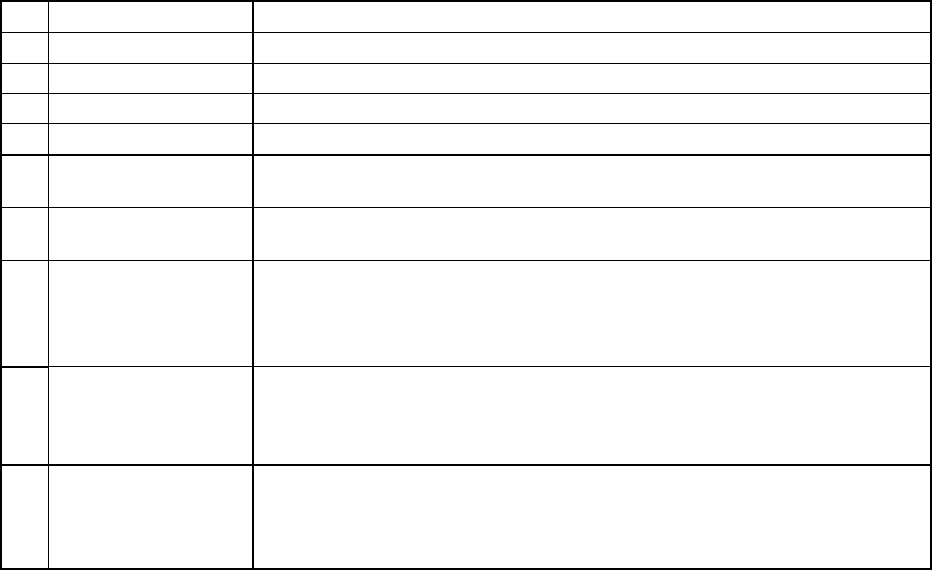
(2) Display items
No. Item Description
1 Component name Displays the component name list.
2 Pack. Displays the packaging style list.
3 Ctrg Displays the centering method list.
4 Nzl. Displays the available nozzle number list.
5 Try Displays the menu that asks you whether to perform a trial operation or
not.
6 Place Shows the number of placements of this component (by referring to the
placement data).
7 Pick Represents the level of completion of all pick data of the applicable
component.
"OK" denotes all the pick data of the applicable component is completed,
while "NG" denotes any pick data is incomplete
8 Compo
Represents the level of completion of all pick data of the applicable
component.
"OK" denotes all the pick data of the applicable component is completed,
while "NG" denotes any pick data is incomplete
9 VIsion When “VCS” is selected as the centering method, this column indicates
whether Vision data is completely created or not. If completed, “OK”
appears. Otherwise, “NG” appears. When “Laser align” is selected as
the centering method, “**” appears on this column.
<5> Cnvr (Conveyor) menu
This command loads and unloads the PWBs.
The operation is the same as that for the PWB data.
<6> Meas. (Measurement) menu
For details, see “Measurement menu”.
<7> Exit menu
The same as the production end of PWB data.
5 − 78
5.6 Pick Data
The pick data establishes the types of component feeders used - whether they are the
tape feeders, stick feeders, or tray holder.
It also defines the position of the component feeders.
It also establishes the layout of these feeders, and the position at which components
are picked up.
For the component angle, it is the angle viewed from the supply side.
5.6.1 Setting range
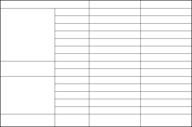
(1) Layout range
The tape feeders, stick feeders, or tray holders are to be mounted onto the
machine by inserting each feeder pin into the feeder mount holes. The following
table shows the possible locations for the feeders to be installed.
Feeder type Bank F Bank R
8 mm 1 ~ 39 1 ~ 39
12 mm 1 ~ 38 2 ~ 39
16 mm 1 ~ 38 2 ~ 39
24 mm 1 ~ 37 3 ~ 39
32 mm 1 ~ 36 4 ~ 39
44 mm 1 ~ 33 7 ~ 39
Tape feeder
56 mm 1 ~ 33 7 ~ 39
TYPE-N 1 ~ 38 2 ~ 39 Stick feeder
TYPE-W 1 ~ 35 5 ~ 39
BF10 1 ~ 39 1 ~ 39
BF11 1 ~ 39 1 ~ 39
BF12 1 ~ 39 1 ~ 39
BF25 1 ~ 39 1 ~ 39
Bulk feeder
BF28 1 ~ 39 1 ~ 39
Tray holder Installation is impossible All the lanes used
on the rear.