KJ-01.02.Instruction Manual.REV.02.pdf - 第177页
5 − 81 (2) Init ial scr een The dat a generat ed in the placement data and component dat a is automatically enter ed for “Component nam e” and “Pack .”. W here no data entry is requir ed because of pack age, an asterisk …
5 − 80
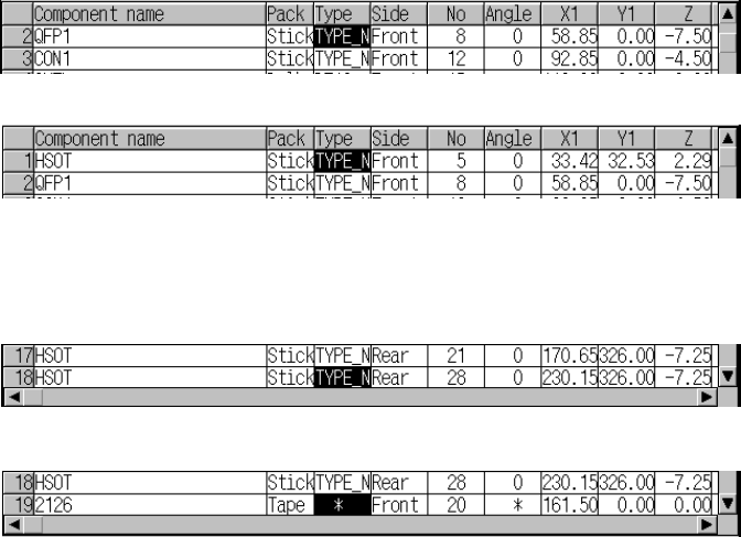
1) Cursor movement range
Column direction: the column on which a component name is displayed.
Row direction: row from the “Type” to “Use.”
2) The cursor moves to the item which requires no entry
You can move the cursor to the menu item on which “*” is displayed, but
cannot enter any value to it.
3) Moving to the beginning and end of the line
The HOME key accesses the left-hand half screen of the listing and
moves the input field to the “Type” cell.
The END key accesses the right-hand half screen of the listing and
moves the input field to the “Use” cell.
4) Up-down scroll
If the ↑ key is pressed when the cursor is located on the bottom line within
the data display area of a window. the screen scrolls up one line.
Press the ↑ key.
If the ↓ key is pressed when the cursor is located on the top line within the
data display area of a window, the component ID has been entered on the
next line, but not the first line, the screen scrolls down one line.
Press the ↓ key..
5) Mutually exclusive entry
If a value is not be set for a mutually exclusive entry item, a pop-up menu
appears automatically allowing you to select an option from among the
menu items.
After the selection is made, the cursor stays at the cursor position. If you
wish to make a change, press the Edit key (F2), which pops up a menu,
allowing you to select an item again. If a settings have previously been
made, the dialog box does not appear until the Edit key (F2) is pressed,
even if the cursor is located at this entry.
5 − 81
(2) Initial screen
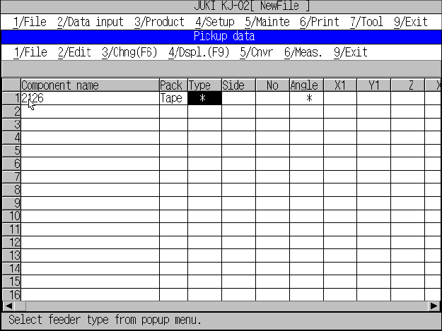
The data generated in the placement data and component data is
automatically entered for “Component name” and “Pack.”. Where no data
entry is required because of package, an asterisk (*) appears in the
corresponding cell. Figure 5.6.2.3 shows the initial left-hand half listing of
pick data.
Figure 5.6.2.3 Pick data initial screen: Left-hand half
5 − 82
5.6.3 Entering tape component data/bulk component data
Different numbers of mounting holes are taken up and set according to the type of
the tape feeder.
- The tape feeder/bulk feeder types and the hole positions occupied to install a feeder
Table 5.6.3.1
Tape feeder and bulk feeder type Number of mounting holes occupied
8mm 2
12mm 3
16mm 3
24mm 4
32mm 5
44mm 8
56mm 8
Bulk feeder 2
(1) Side (Supply)
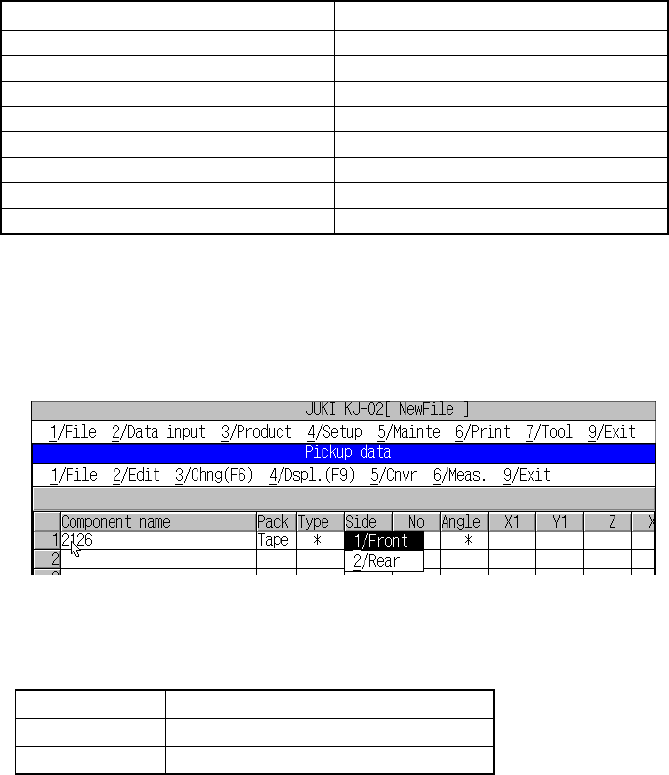
This parameter determines whether the tape feeders and bulk feeders is
mounted on the front or rear side of the machine. Figure 5.6.3.1 shows the
screen on which “Side” can be set.
Figure 5.6.3.1 Tape feederand bulk feeders “Side” setting screen
Descriptions of “tape/stick/bulk” settings
Setting Description
1/Front Components supplied at the front
2/Rear Components supplied at the rear
If items (X1, Y1, or Z) on the right of the numbers have already been set, they
will be initialized when the corresponding “Side” setting is changed.
Any 32-mm paper tape feeder cannot be installed on the rear side. (“Front”
appears by default.)
(2) No
This parameter sets the mounting position of the component feeder.
The tape feeder, stick feeder and bulk feeder are equipped with a fixing pin on
their end. This pin fits into the feeder mounting hole so that the feeder can be
placed in position. For this parameter, define the feeder mounting hole number.
If a new number is entered or the number is changed, X1, Y1, and Z are
automatically recalculated and the results shown on the screen. As soon as a
number is entered, overlap is checked for the existing tape feeders, bulk feeder,
stick feeders, and tray holders. If the same number already exists, the entry is
rejected with an error message shown on the screen.