KJ-01.02.Instruction Manual.REV.02.pdf - 第341页
10 − 16 10.4.6 Others 10.4.6.1 A TC control W hen you select the [6/Others] command on the menu bar , and then the [1/A T C control] com mand on the displayed menu, t he dialog box f or contr olling the A TC appears on t…
10 − 15
10.4.5 Vision
10.4.5.1 Live image control
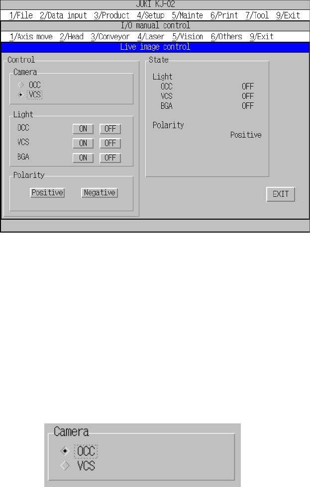
When you select the [1/Live image control] command on the “5/Vision” menu, the
“Live image control” dialog box appears as shown in Figure 10.4.5.1.1.
Figure 10.4.5.1.1 Live image control screen (Screen example when you use a KJ-02)
− Camera
Select a camera whose image is to be displayed by clicking the corresponding
radio button.
Note that you cannot select a unit whose view type is not set (that is, not
installed) with the "Option" menu of the MS parameters.
This selection will not affect the setting of the "Device enable" dialog box invoked
from the Machine setup menu (you can select a unit not).
(You can select a unit that is not to be used on the “Use unit” menu.)
Live image control camera selection dialog box
− Polarity
By clicking the corresponding radio button, you can switch the polarity of image
displayed on the monitor: positive or negative
The state of the back light is updated when the back light is controlled completely.
10 − 16
10.4.6 Others
10.4.6.1 ATC control
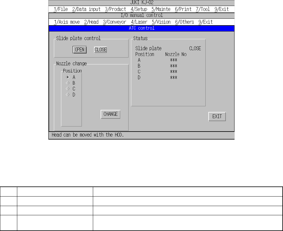
When you select the [6/Others] command on the menu bar, and then the [1/ATC
control] command on the displayed menu, the dialog box for controlling the ATC
appears on the screen as shown in Figure 10.4.6.1.1.
Each command is described on Table 10.4.6.1.1.
Figure 10.4.6.1.1 “ATC control” dialog box
Table 10.4.6.1.1 Description of each command.
No. Command Description
1 Slide plate control Controls the slide plate (OPEN/CLOSE).
2 Nozzle change Replaces the current nozzle with the nozzle you specified.
3 Status Displays the condition of the slide plate and the number of a nozzle located
at each ATC position.
When you select a button displayed on the dialog box above, the specified control
operation starts. The controlled condition is displayed in real time.
When you click the <CHANGE> button on the “Nozzle change” window, a nozzle
whose position: A to D is checked is replaced with another one.
10 − 17
CAUTION
The specified nozzle starts being replaced immediately after you click
the <CHANGE> button.
To avoid risk of injury, do not place your hand in the machine, nor
move your face or head close to the machine during operation.
Before clicking the <CHANGE> button, check to see if there is no one
who is working the internal parts of the machine.
Before clicking the <CHANGE> button, check to see if there is no one
who is near the machine and can be injured when the machine warms
up.
Before clicking the <CHANGE> button, check to see there is no
obstacle (tools and jigs) attached or left in the machine that may
prevent any part inside the machine from operating.
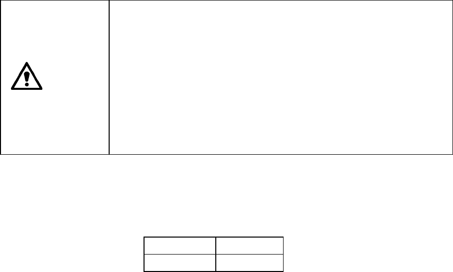
The positions from A to D displayed on the “Nozzle change” window of the dialog box
shown in Figure 10.4.6.1.1 are assigned as shown below when you face the front of
the machine.
A B
C D
“**” displayed as the nozzle number on the “Status” window indicates that the
corresponding nozzle is not assigned on the Setup screen. The leftmost * mark
indicates the position of the ATC to which the nozzle attached on the current head is
assigned.