KJ-01.02.Instruction Manual.REV.02.pdf - 第264页
7 − 14 5. Adjust t he noise cut level. Use t he +Y and/or –Y k ey of t he HOD to adj ust the noise cut level around a mark so that the m ark can be viewed clearly , and the noise around t he mark can be reduced as much a…
7 − 13
Figure 7.3.2.2
3. Use the +Y and/or –Y key of the HOD to select which direction the recognized
image data is to be rotated: positive or negative. After selecting the rotating
direction, press the ENTER key.
Note: The machine detects a white part as a mark. Whether the mark is
recognized as white or black with respect to the board color depends on
the contrast between the mark and the board, and on the light level for
the camera’s field of view. Normally, the mark is recognized as white. If,
however, there are lands, patterns, or silk printings around the field of
view of camera, the mark may be recognized as black with respect to the
board color. In this case, normal correction is impossible. Reverse the
black and white by pressing the +Y or -Y key on the HOD so that the
mark appears as white. If a mark is recognized as black against the
board, press the +Y or -Y key to reverse the black and white so that the
mark can be recognized as white.
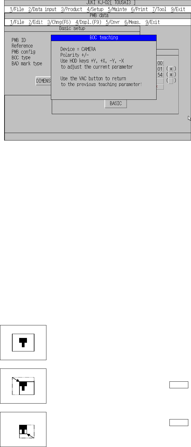
4. Adjust the scale frame.
Set the top, left, bottom and right sides of the scale frame with the direction key
(+Y, -Y, +X and/or –X) to adjust the size of the scale frame
The FAST key changes the moving distance of the scale frame.
The camera picture and a rectangle frame appear.
Set the top and left scale frames first. Adjust them
so that they match with the top and left of the mark.
When adjustment is complete, press the ENTER
key.
In the same manner as above, set the bottom and
right scale frames.
When adjustment is complete, press the ENTER
key.

7 − 14
5. Adjust the noise cut level.
Use the +Y and/or –Y key of the HOD to adjust the noise cut level around a mark
so that the mark can be viewed clearly, and the noise around the mark can be
reduced as much as possible. After adjusting the noise cut level, press the
ENTER key to confirm it.
6. Select “PR” as a mark on the mark selection screen.
Use the +Y or –Y key of the HOD to select “PR”, and press the ENTER key to
confirm it.
Note: Only when you select a board mark, you can select “PR”. When you
select an IC mark, the machine automatically skips “PR”, and you cannot
select it.
7. Adjust the center of the template.
Move the crosshair cursor within the scale frame to adjust the center of the
template.
Use the direction key (+Y, -Y, +X and/or –X) to move the cursor. After adjusting
the center, press the ENTER key to confirm the center position.
Note: If you select a mark other than PR, the machine will not set the center of
the template.
8. Adjust the mark detection range.
Use the direction key (+Y, -Y, +X and/or –X) to adjust the scale frame.
After adjusting the scale frame, press the ENTER key to confirm it.
Note: To readjust the scale frame, press the VAC ON/OFF key of the HOD to
display the previous setting screen.
You have finished recognition teaching of the user-defined template here.
After recognition teaching, “(*)” appears next to the mark data, and it indicates
that the mark data is taught already. Perform recognition teaching for all of the
marks to be used.
When you press the CANCEL key of the HOD while the machine is teaching, it
finishes the current teaching operation. (Note that data you have entered so far
becomes invalid.)
Even though you press the CANCEL key, any device will not move.
[ ] ●
[ ] ○
[ ] ■
[ ] □
[ ] ▲
[ ] △
[ ] ▼
[ ] ▽
[ ] ◆
[ ] ◇
[ ] +
7 − 15
Notes on setting of a template
1) You cannot register any IC mark as a user-defined template.
2) Check to see if there is no pattern similar with the template set inside the
detection frame.
3) Specify 0.5 to 3 mm as the pattern size in the same manner as the standard
mark.
4) Use the designed values (CAD data) as the coordinate value. With the user
defined template data, the center position of the pattern cannot be calculated
correctly. Since the mark is taught with moving the cross-hair cursor, the user
defined position becomes the center position (the normal mark generates no
error because the calculated center position becomes the center position of the
pattern).
5) The vision copy of the user defined template cannot be made.
6) The machine stores user-defined template data to the VCS as a full-path
production program name. If an error message “Specified template data full.
Delete not used template data.” appears on the screen, select the [1/File]
command on the menu bar, select the [5/File maintenance] command on the
displayed “File” menu, and select the [Delete template] command in this order to
delete unnecessary template data.
7) If you use a production program that uses a user-defined template with another
mounter, perform teaching operation again.
8) If you want to perform file operation such as copying and renaming of a
production program that is stored in the flash memory, be sure to select the
[1/File] command, and then the [5/File maintenance] command
9) The length of a production program name including a path should be 32
characters or less.
(If you enter a production program name whose length is longer than 32
characters, the interface error between the VCS and the machine occurs, and
the machine cannot create any template data.)
Patterns which can be registered as the user defined template
1) Patterns which can be registered as the user defined template
① Wiring pattern
② Pad and land pattern where no screen is printed (no solder paste is put)
③ PWB marks other than JUKI standard marks (whole or part)
2) Notes on registration as the user defined template
① Through hole and pier hole
Since the pattern generation process is different from the holing process, the
same positioning cannot be always achieved. (The hole position is
undefined for a pattern.)
To register the template based on the through hole or pier hole, include the
wiring pattern around the hole.