KJ-01.02.Instruction Manual.REV.02.pdf - 第92页
4 − 21 (3) Def ault values Signal light pattern No. Status Red Y e llow Green Buzzer 1 Initial state (Pow er on) All colors light. ■ ■ ■ OFF 2 Desktop Y ellow lights. — ■ — OFF 3 File operation Y ellow lights. — ■ — OFF …
4 − 20
4.3.9 Signal light
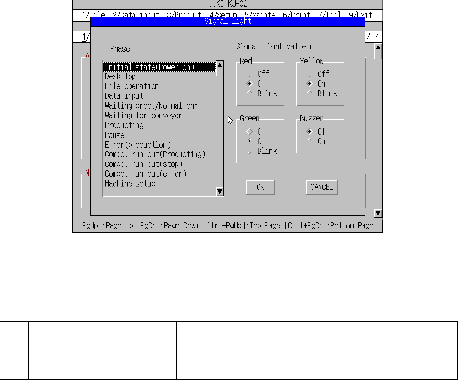
When you select the [9/ Signal light] command from the [1/Set up group] menu, the
“Signal light” dialog box appears on the screen as shown in Figure 4.3.9.1.
Figure 4.3.9.1 Signal light setting dialog box
(1) Setting items
No. Item Description
1 Signal light pattern
(Red, Yellow, Green)
Sets the light pattern of the signal light for each operation phase.
2 Signal light pattern (Buzzer) Sets ON/OFF of the buzzer for each operation phase.
(2) How to set
① Signal light (Red, Yellow, Green)
– Using the radio button, set on, off, or blink.
② Buzzer
– Using the radio button, set off or on.
4 − 21
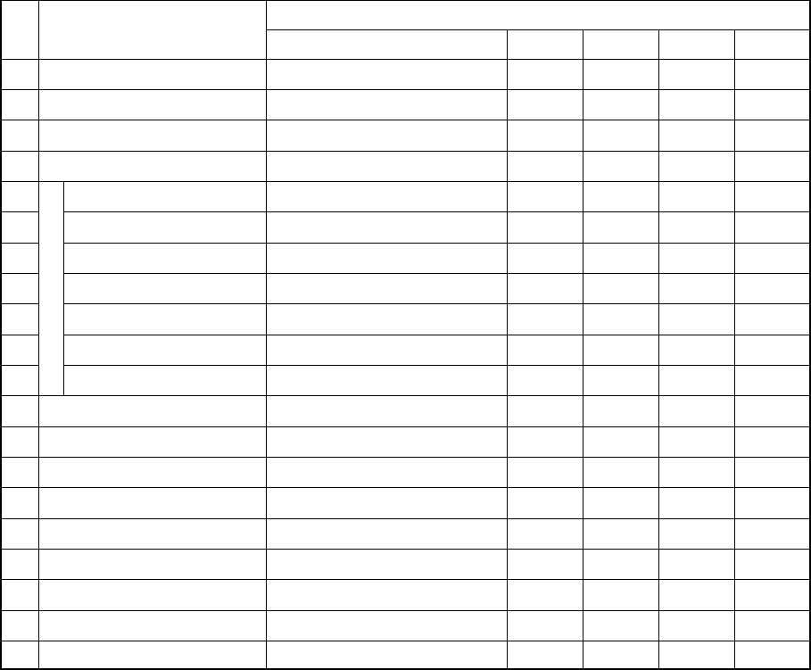
(3) Default values
Signal light pattern No. Status
Red Yellow Green Buzzer
1 Initial state (Power on) All colors light.
■ ■ ■
OFF
2 Desktop Yellow lights. —
■
— OFF
3 File operation Yellow lights. —
■
— OFF
4 Data input Yellow lights. —
■
— OFF
5 Waiting prod./Normal end All colors light.
■ ■ ■
OFF
6 Waiting for conveyor Green flashes. — —
□
OFF
7 Producing Green lights. — —
■
OFF
8 Pause Yellow lights. — —
■
OFF
9 Error (production) Red lights.
■
— — OFF
10 Compo. run out (stop) Red lights and yellow flashes.
■
□
OFF
11
Production
Compo. run out (error) Red lights and yellow flashes.
■ □
— OFF
12 Machine setup Yellow lights. —
■
— OFF
13 Manual control Yellow lights. —
■
— OFF
14 Warm up Yellow lights. —
■
— OFF
15 Idle mode Yellow lights. —
■
— OFF
16 Printing Yellow lights. —
■
— OFF
17 Return to home position Yellow lights. —
■
— OFF
18 Emergency stop Red lights.
■
— — OFF
19 Error (Expect production) Red lights.
■
— — OFF
20 Others Red lights. — — — OFF
■: ON
□: Flashes
—: OFF
* The initial status of the machine means the duration before it is set ready to
be operated after power is turned on. The desktop is the initial display of the
screen after the machine quits the initial status.
(4) Signal Light Buzzer
A signal light buzzer is optional, so be sure to set the Buzzer radio button of the
signal light pattern to OFF when you use a signal light not equipped with a
buzzer.
The buzzer sounds when the machine enters each status described in Table
above only if the Buzzer radio button of the signal light pattern is set to ON. To
stop the buzzer, press any key on the front panel such as the START key and
STOP key. In this case, the key you pressed just stops the buzzer, and does not
perform its own function.
4 − 22
4.3.10 Nozzle data installation
To enable the expanded nozzle, install the data on the nozzle to the machine. When
you install the data to the machine, you can select the nozzle whose data is installed
on the ATC nozzle setup screen or Component data screen.
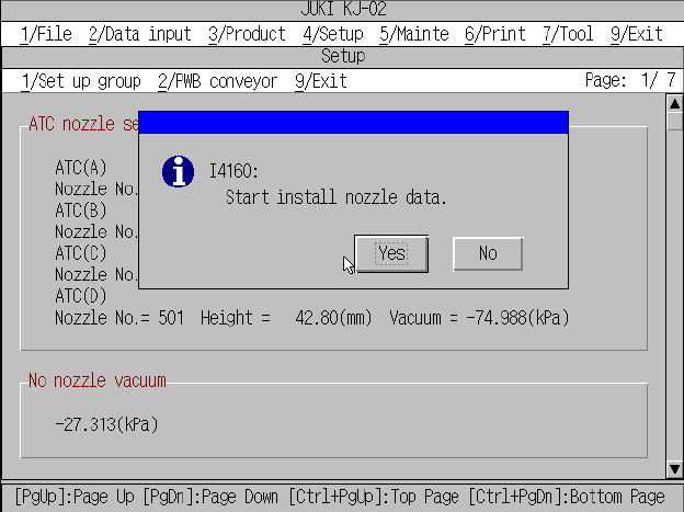
When you select the [B/Nozzle data installation] command, the message appears as
shown in Figure below.
If you do not install any nozzle data to the machine, click the <No> button to quit the
nozzle data installation process.
When you click the <Yes> button, the machine starts installing the nozzle data to the
machine.
Figure 4.3.10.1 Nozzle data installation dialog box
When the machine starts installing the nozzle data, the dialog box shown in Figure
4.3.10.2 appears on the screen.
Insert a floppy disk on which a nozzle data file is stored into the floppy disk drive, and
click the <OK> button.