KJ-01.02.Instruction Manual.REV.02.pdf - 第17页
1 − 1 CHA PTER 1 GENERA L 1.1 Features and Specifications This machine is an SMD chip mounter of compact design: it s main unit dim ensions are 700 mm × 375 mm × 1300 mm (width/dept h/height ). Its t wo centering methods…

v
CHAPTER 13 HANDLING THE FEEDERS AND OPTIONS
13.1 Replacement of the Tape Feeder.................................................................... 13-1
13.1.1 Replacement of the tape feeder
(8 mm, 12 mm, 16 mm, 24 mm, and 32 mm) ..................................... 13-1
13.1.2 Replacement of 32-mm adhesive tape feeder .................................... 13-2
13.2 Replacement of the Bulk Feeder..................................................................... 13-3
13.3 Replacement of the Stick Feeder .................................................................... 13-4
13.4 Procedure for Mounting the Matrix Tray Holder on the Feeder ....................... 13-5
13.5 Handling the Bad Mark Sensor........................................................................ 13-6
CHAPTER 14 MAINTENANCE
14.1 Daily Routine Checks....................................................................................... 14-1
14.1.1 List of daily routine checks .................................................................. 14-1
14.2 Check............................................................................................................... 14-2
14.2.1 Air pressure......................................................................................... 14-2
14.2.2 Piping and joint.................................................................................... 14-3
14.2.3 Unit air cylinder.................................................................................... 14-3
14.2.4 Air filter (Head).................................................................................. 14-5
14.2.5 Transport belt ...................................................................................... 14-6
14.2.6 Transport pulley................................................................................... 14-7
14.2.7 Notice on Electricity............................................................................. 14-8
14.3 Cleaning........................................................................................................... 14-9
14.3.1 XY axis direct drive unit....................................................................... 14-9
14.3.2 Transport sensors ............................................................................... 14-11
14.3.3 Laser align sensor (MNLA/FMLA head).............................................. 14-12
14.3.4 Nozzle.................................................................................................. 14-13
14.3.5 ATC ..................................................................................................... 14-17
14.3.6 Feeder bank ........................................................................................ 14-18
14.3.7 Z slider shaft........................................................................................ 14-18
14.3.8 OCC (Polarizing filter).......................................................................... 14-19
14.3.9 Glass of VCS (only for a KJ-02) .......................................................... 14-20
14.3.10 Trackball.............................................................................................. 14-21
14.4 Lubrication ....................................................................................................... 14-22
14.4.1 XY-shaft direct drive unit ..................................................................... 14-22
14.4.2 Transport guide shaft........................................................................... 14-23
14.4.3 PWB stopper part................................................................................ 14-23
14.4.4 Ball screws and Linear way (Head part) (KJ-02)................................. 14-24
14.4.5 Backup table........................................................................................ 14-25
ERROR MESSAGES TABLE
........................................................................................ 1
1 − 1
CHAPTER 1 GENERAL
1.1 Features and Specifications
This machine is an SMD chip mounter of compact design: its main unit dimensions
are 700 mm × 375 mm × 1300 mm (width/depth/height). Its two centering methods
that do not have to touch any component, by laser beam and the Visual Centering
System (VCS), allow components such as a chip and fine-pitch IC to be placed on a
board highly precisely.
1.1.1 Features
− Equipped with a laser alignment head (LAHD) as a standard device that allows
components from a 0603 chip to a 20 mm × 20 mm or 23.5 mm × 11 mm
component to be placed on a board in 0.9 seconds per component (when optimal)
highly precisely.
− Equipped with a VCS as a standard device also that has the fixed type of side light,
which allows the machine to center the maximum 24 mm × 24 mm components
such as a 0.3-mm pitch QFP, BGA and FBGA: this realizes the highly-precise
placement of components in 2 seconds per component when optimal.
− Equipped with an offset correction camera as a standard device, which allows the
machine to recognize a PWB pattern with the pattern matching function or
recognize various types of board marks.
− Frames of high rigidity are adopted for the XY unit, and the full-closed loop control
with the magnetic scale enables highly precise placement of components that is
available with a KE-series chip mounter.
− The standard device, automatic PWB transport device, which can handle up to 8”
×6” (203.2 mm × 152.4 mm) board, allows you to set a board without putting your
hand inside the machine.
− With succeeding the operability of a KE-750/760, a track ball is provided as an
optional device.
1 − 2
1.1.2 Centering system
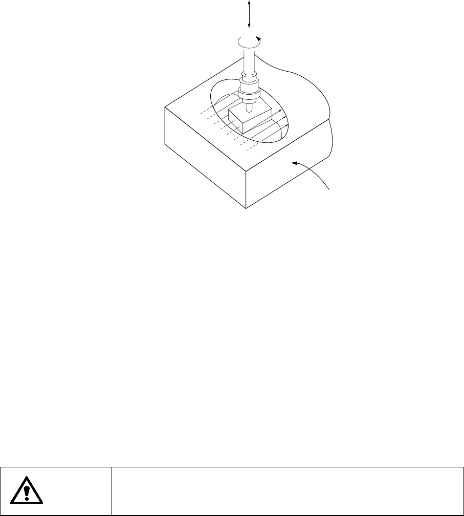
Instead of using conventional mechanical centering system, this machine uses
touchless centering system where laser align sensor is used to read the position and
angle of components. This can be achieved by detecting the shade of the
components created by the laser rays applied horizontally to the components.
Z
θ
Figure 1.1.2.1
By moving Z-axis up and down, a component is picked with vacuum, and the laser is
applied to the component. A shade is made where the laser is obstructed by the
component. By turning the component along θ-axis, the shade changes.
According to the change of the shade, offsets of the position and angle of the picked
component are calculated. These offsets are corrected when mounting.
The laser align sensor conforms to IEC825 Class 1 and CDRH Class 1 regulations.
The laser align sensor can be used safely as far as it is used by following the
instructions described in this manual.
CAUTION
Any operation of controls and adjustments which is not described in
this manual can cause an excessive exposure of laser lays which may
be dangerous to human bodies.
Laser align sensor