KJ-01.02.Instruction Manual.REV.02.pdf - 第196页
5 − 100 • Set the measurem ent item s on the “Measurement Conditions” screen. • W hen you select the Measurement button, t he system executes measurement , then displays the measur ement r esult when it is complete. Note…
5 − 99
5.7.2 Components measurement
5.7.2.1 Measurement operations
(1) How to execute measurement
− When you select the [6/Meas.] command on the Component data screen,
and then the [1/Single measurement] command on the displayed menu, the
“Measurement” conditions setting screen appears.
− The machine measures the items whose check boxes are checked.
− You can select two or more items if they are enabled. The enabled items
vary depending on the component type you selected.
(2) Overview of the operation
− When you select the [6/Meas.] command on the Component data screen,
and then the [1/Single measurement] command on the displayed menu, the
“Measurement” conditions setting screen appears.
Notes:
−
−−
−
This function cannot work if both Pick data and Component data
are completely entered.
−
When you click the <MEAS> button, the nozzle moves to the
component pick-up position based on the OCC as the reference
position.
−
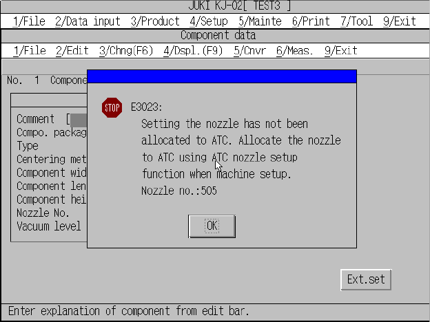
If a nozzle set on Component data is not allocated to the ATC,
the following screen appears.
No nozzle error confirmation screen
Change the current nozzle to a nozzle that is allocated to the ATC on the
Component data, or allocate the current nozzle to the ATC on the
Component data, and select it again.
5 − 100
• Set the measurement items on the “Measurement Conditions” screen.
• When you select the Measurement button, the system executes
measurement, then displays the measurement result when it is complete.
Note: If the component pick up error, or laser or VCS recognition error
occurs, the error type is displayed without measurement result.
• When you select the OK button on the Measurement result screen, the
measurement result is stored as the “Component data”, then the system
returns to the Measurement conditions screen.
• When you select the Cancel button on the Measurement result screen, the
system returns to the Measurement conditions screen without storing the
measurement result.
• Manual teaching and input of the pick position coordinate are possible on the
Measurement conditions screen. If “Stored as pick data” is checked, the pick
position can be stored as the Pick data.
Note: The pick position of the components supplied with the tray cannot be
stored as the “Pick data”.
• When you select the NEXT or PREVIOUS button of the HOD or the F5 or
F6 key on the Measurement conditions screen, the system can move to the
alternative component.
CAUTION
The OCC starts moving to the component pick-up position
immediately after you click the <MEAS> button.
To avoid risk of injury, do not place your hand in the machine, nor
move your face or head close to the machine while you are
operating the HOD.
Before clicking the <MEAS> button, check to see if there is no one
who is working the internal parts of the machine.
Before clicking the <MEAS> button, check to see if there is no one
who is near the machine and can be injured when the machine
warms up.
Before clicking the <MEAS> button, check to see there is no
obstacle (tools and jigs) attached or left in the machine that may
prevent any part inside the machine from operating.
5 − 101
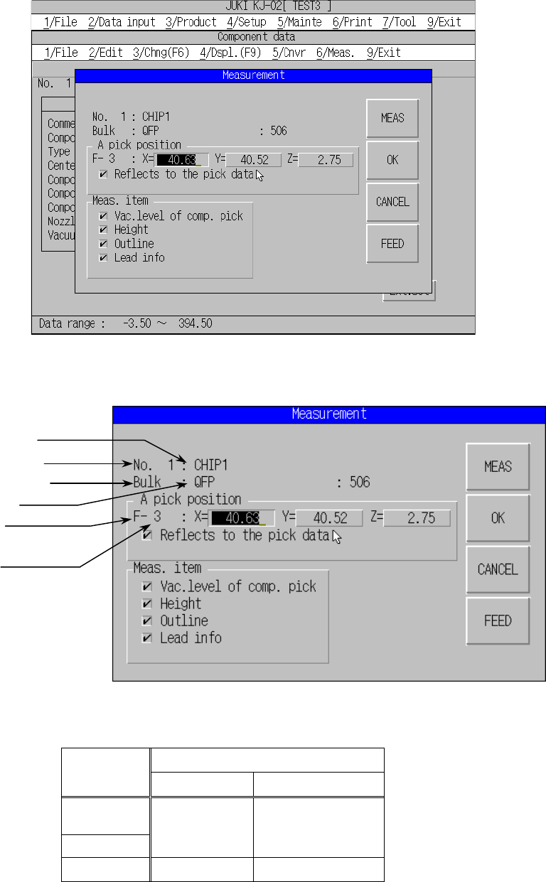
5.7.2.2 Measurement conditions setting
A screen as shown below appears when “Single Measurement” is selected on the
menu.
Component data measurement screen
(1) Execute position
Explanation of measurement screen
Pick position #-##
Supplied
with
# ##
Tape
Bulk
Stick
F Front side
R Rear side
Hole number
Holder
R Rear side
**
Hole number
Component number
Component package
Pick position
Front side →F
Rear side →R
Component type
Component name