KJ-01.02.Instruction Manual.REV.02.pdf - 第162页
5 − 66 – Moving through the i nput items – The def ault values are set f or expanded setting s and there is no need of changing. The def ault values are determ ined by the setting of component s, centering method, and co…
5 − 65
<6> Working on the expanded windows
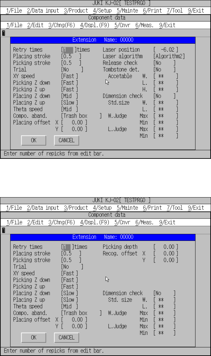
The extension window displayed when the centering method is set to “Laser
algorithm” is shown in Figure 5.5.1.17, and that set to “VCS” is shown in Figure
5.5.1.18.
Figure 5.5.1.17 Expanded window for laser centering
Figure 5.5.1.18 Expanded window for vision centering
5 − 66
– Moving through the input items
– The default values are set for expanded settings and there is no need of
changing.
The default values are determined by the setting of components, centering
method, and component package. If any one of these items which affect the
expanded settings has been changed after changing the values of the items
of the expanded setting, the values are reset to the default values of the
changed item.
↑ key: Clockwise
↓ key: Counterclockwise
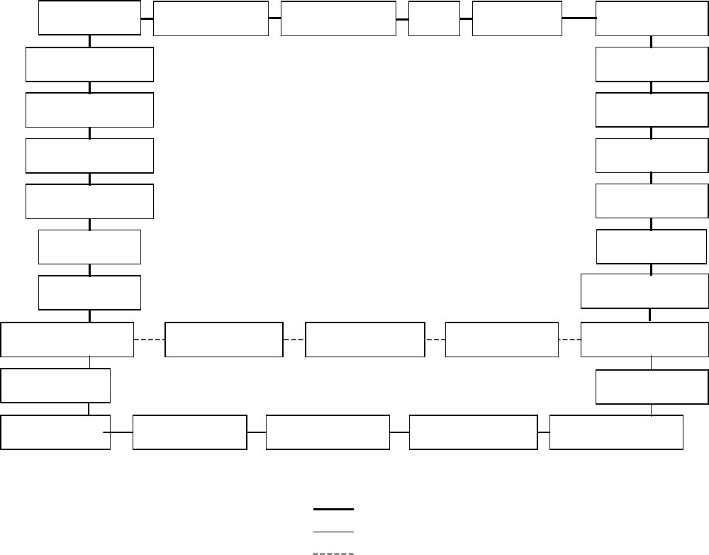
Figure of entries to be moved
Picking Z
d
Picking Z up
Placing Z
d
Placing Z up
Laser algorithm
Placing offset X
Placing offset Y
Retry times
Placing stroke Picking stroke Trial XY speed
Theta speed
L. Judge Min
L Judge Max
W. Judge Min
W. Judge Max
Std. Size W.
Std. Size L.
Laser height
Acceptable
H
Dimension check
C
ompo.
abandonment
Picking depth
Recog. offset Y Recog. offset X
Release check Acceptable W. Tombstone det. Acceptable L.
Common to the laser and VCS centering methods
Only for the laser centering method
Only for the VCS centering method
5 − 67
No. Item Reset item Reset value (Default value)
1 Retry times None 1
2 Placing stroke None 0.5 mm (0.2 mm for a 0603 chip)
3 Picking stroke None 0.5 mm (0.2 mm for a 0603 chip)
4 Trial None No
5 XY speed None Depending on the conditions.
6 Picking Z down None Depending on the conditions.
7 Picking Z up None Depending on the conditions.
8 Placing Z down None Depending on the conditions.
9 Placing Z up None Depending on the conditions.
10 Theta speed None Depending on the conditions.
11 Placing offset Component type
Component height
See next page.
12 Laser position Component type
Component height
See next table.
13 Laser algorithm Component type
Component height
See next table.
14 MTC Auto teaching None No
15 Picking depth None 0.0 mm (only for the VCS centering method)
16 Recog. offset None 0.0 mm (only for the VCS centering method)
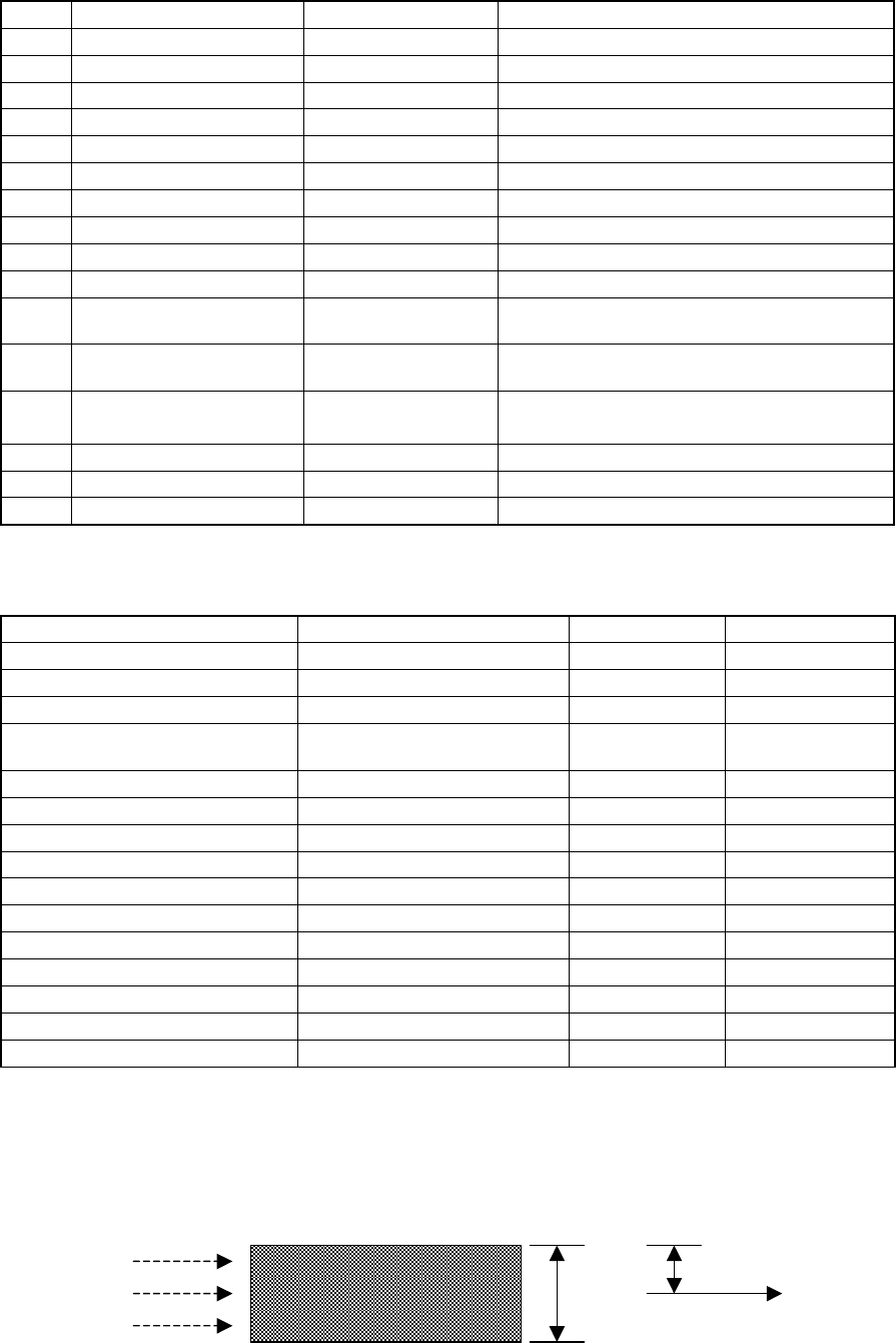
– Depending on the component type and component dimensions, the default values
for the laser height, placing offset, and laser algorithm are set.
Component type Laser recognition algorithm Laser height Placement offset
Square chip Algorithm 1 (14, -14) 0.5xT 0.00
MELF Algorithm 1 (14, -14) 0.5xT 0.00
SOT Algorithm 1 (14, -14) 0.15mm 0.00
SOP, TSOP, TSOP2, SOP
(equipped with a heat sink)
Algorithm 2 (14, 14) 0.7xT 0.00
QFP Algorithm 2 (14, 14) 0.7xT 0.00
PQFP (BQFP) Algorithm 1 (14, -14) 0.45xT 0.00
SOJ Algorithm 2 (14, 14) 0.65xT 0.00
PLCC (QFJ) Algorithm 2 (14, 14) 0.65xT 0.00
Aluminum electrolytic capacitor Algorithm 1 (14, -14) T-0.45 0.00
BGA Algorithm 2 (14, 14) 0.86xT 0.00
Network resistor Algorithm 1 (14, -14) 0.5xT 0.00
Trimmer Algorithm 1 (14, -14) T-0.7 0.00
Connector Algorithm 1 (14, -14) -1mm 0.00
IC socket Algorithm 1 (14, -14) 0mm 0.00
Other components Algorithm 1 (14, -14) 0.5xT 0.00
Note 1: T in the table avobe is the height of components.
Note 2: Although the machine sets the laser height based on the shape of a component by
default, you may have to modify this default setting depending of the thickness of the
molded section of an aluminum electrolytic capacitor or trimmer (see page 1-5).
Figure of laser height
T
Component
Laser
Laser height