KJ-01.02.Instruction Manual.REV.02.pdf - 第253页
7 − 3 7.2 Teaching Coordinates 7.2.1 Basic operating procedure Coordinates teaching is gener ally done by the following procedure. 1. Move the cursor to the desir ed data position. For X- and Y- axes, the coordinates of …
7 − 2
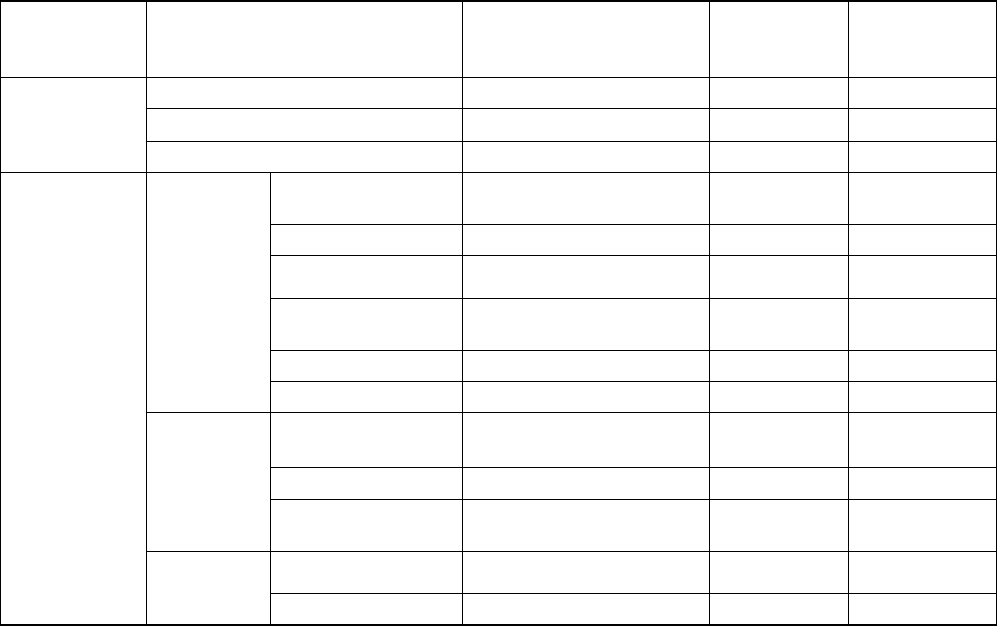
(2) Teaching item details
Table 7.1.2 KJ-01/02 Teaching items
Mode during
teaching
Input data item Data origin
Corrected by
Boc alignment
Corrected by
Feeder bank
recognition
Reference pin position XY coordinates origin
Shape clamp position XY coordinates origin
Machine setup
Component scrap position XY coordinates origin
PWB reference Reference pin position or
shape clamp position
K
Frist circuit position Board reference position
BOC mark position Board reference position
BOC mark recognition
parameter
Bad mark position
PWB data
PWB height
Placement position
IC mark position
Placement
data
IC mark recognition
parameter
Pick position XY
K
Production
program
Pick data
Pick position Z
7 − 3
7.2 Teaching Coordinates
7.2.1 Basic operating procedure
Coordinates teaching is generally done by the following procedure.
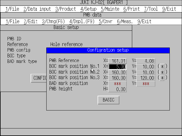
1. Move the cursor to the desired data position.
For X- and Y-axes, the coordinates of both axes can be taught.
While, Z-axis must be individually taught.
Figure 7.2.1.1
2. Using the HOD device keys, select the device to be taught.
If an illegal device is selected, an alarm beeps, prompting the operator to
reselect the device.
If coordinates have previously been entered, the selected device moves to that
coordinate position.
If not, the device does not move.
If the head is selected and a different nozzle is installed other than that used in
teaching, the nozzle is replaced.
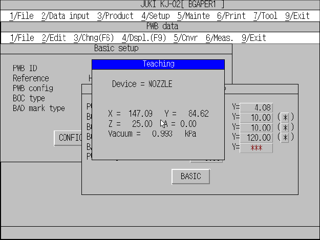
In this case, the following information is shown on the screen.
– Selected device name
– X/Y coordinates of the selected device
– Z coordinate of the selected device
– θ -axis of the selected device
– Vacuum value of the selected device
The LED of each TEACH IN key (XY, Z) on the HOD lights up when
pressed, indicating what to teach.
7 − 4
Figure 7.2.1.2
3. Using the axis drive keys on the HOD (XY, Z), move the selected device.
As the device is moved, the numerals (coordinate values, etc.) shown on the
screen change.
An alarm beeps when the device reaches its motion limit, warning that the device
cannot be moved further.
The FAST key on the HOD may be used to change the motion speed of the
X-and Y-axes. The speed of the Z -axis cannot be changed.
4. When the device reaches the desired position, press the ENTER key on the
HOD to store obtained data (the coordinates of this point) into the machine
memory.
This completes the coordinates teaching procedure.
<Supplementary explanation for teaching speed>
1) Teaching speed selection
Pressing the FAST key on the HOD lights up the LED, and the motion speed
of the X-, and Y-axes changes from low to medium. To change the motion
speed back to low, press the FAST key a second time. The LED goes out
and the speed changes to low.
2) Step-by-step movement and continuous movement
Holding down an arrow key on the HOD continues the motion, and releasing
the key stops the motion. For step-by-step motion, do not hold down the key
but press it repeatedly.