KJ-01.02.Instruction Manual.REV.02.pdf - 第226页
6 − 22 2) Number of leads Range of the number of leads Compo. T y pe Recognition pattern Upper and left corner Upper and right corner Lower and left corner Lower and right corner One-way connector All leads Only the both…
6 − 21
(1) Recognition pattern
1) Selecting the lead recognition pattern
Select a pattern with the radio box.
Note: When you change the recognition pattern with clicking the radio button,
the number of leads is initialized (to the minimum value).
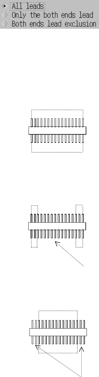
2) Meaning and image of each lead recognition pattern
• All leads: All leads are to be recognized.
• Only the both ends lead: Only leads located on both sides are to be
recognized.
• Both ends lead exclusion: Leads except the specified leads located on
both sides are to be recognized.
Recognized
Recognized
Recognized Recognized
Recognized Recognized
The leads located at the inside are not recognized.
The leads located on the outside are not recognized.
Recognized
6 − 22
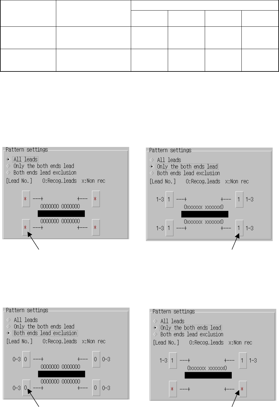
2) Number of leads
Range of the number of leads Compo. Type Recognition pattern
Upper and
left corner
Upper and
right corner
Lower and
left corner
Lower and
right corner
One-way connector All leads
Only the both ends lead
Both ends lead exclusion
*
1-3
0-3
*
1-3
0-3
*
*
*
*
*
*
Two-way
Z lead connector
All leads
Only the both ends lead
Both ends lead exclusion
*
1-3
0-3
*
1-3
0-3
*
*
*
*
1-3
0-3
Table 6.3.3 Range of the number of leads
* The input range of the number of leads to be recognized varies depending
on the number of leads entered on the Vision data screen.
(The displayed number is fixed to “1-3” and “0-3.”)
• Setting example for “All leads” • Setting example for “Only the both ends lead”
• Setting example for “Both ends lead exclusion” • Setting example for “Only the both ends lead”
(One-way lead connector)
You do not have to set the
number of leads.
Specify one or more as
the number of leads
located on both sides.
Specify any number of
leads to be excluded.
The leads located on the
lower side are not set for a
one-way lead connector.
6 − 23
6.4 Setting the Vision Recognition Pattern for an
Outline-To-Be-Recognized Component
6.4.1 Setting the vision recognition pattern
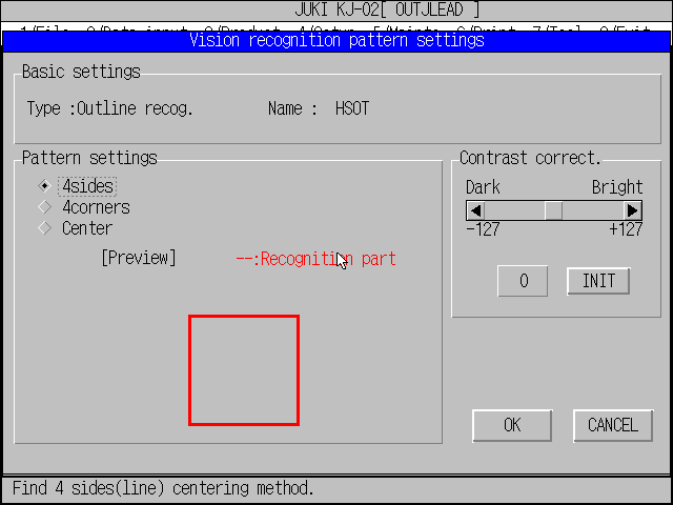
Set the parameter for the recognition pattern of an outline-to-be-recognized
component.
Figure 6.4.1.1 Outline-to-be-recognized component vision
recognition pattern settings dialog box
(1) Setting the recognition pattern
Set the pattern for recognizing an outline-to-be-recognized component with the
VCS.
When you set the recognition pattern, the machine previews it.
Click the radio button corresponding to the desired recognition method.
1) 4sides
Recognizes a component with four sides (straight lines) of a rectangle.
2) 4corners
Recognizes a component with four corners of a rectangle.
3) Center
Requires the center and moment of an object.
(2) Contrast correct.
Set the threshold for correcting the contrast obtained when a component is
recognized.
Use the scroll bar or enter a value in the edit box to set the threshold. This
value corrects the contrast level of the recognized image of a component to
judge the recognition result more strictly or more tolerantly.
When you click the <INIT> button, the threshold is set to the default value (= 0).