KJ-01.02.Instruction Manual.REV.02.pdf - 第367页
13 − 5 13.4 Procedure for Mounting the Matrix T ray Hol der on the Feeder Bank (See Figure 13.4.1.) CA UTION T o avoid any accident caused by sudden activation of the machine, t urn off the power . 1) Grip the side plat …
13 − 4
13.3 Replacement of the Stick Feeder
CAUTION
Do not replace the stick feeder with another one while the X- or Y-axis, or head
is operating. It may cause a serious injury to the operator or damage the
machine itself since the stick feeder touches the operating parts.
Do not dismount the stick feeder while the X- or Y-axis or head is operating.
After you mount the feeders required for producing boards at the position
specified with a production program, mount feeders, which are not used for
production, such as 8-mm tape feeders where no feeders are mounted to
prevent any gap from being generated between the already mounted feeders.
This operation secures your safety since it prevents your finger or hand from
accidentally being slid into such a gap.
Mounting
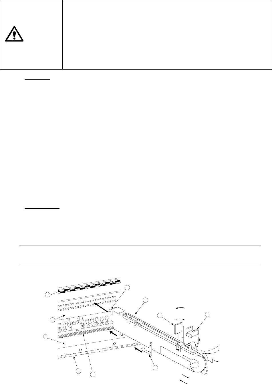
1) Place the bottom of the stick feeder ①on the feeder bank ②.
2) Slide the stick feeder ① toward the positioning hole of the fixing plate ③, and
align the guide pin located on the bottom of the stick feeder with the fixing plate
B⑦ as a guide. Fit the positioning pin on the front of the stick feeder into the
positioning hole of the fixing plate ③. To do so, with releasing the toggle
clamp ⑩ to align the lock holder ⑨ with the V-shaped groove of the lock shaft
⑧, push the front of the stick feeder against the fixing plate. Fix the stick
feeder with the toggle clamp ⑩.
In this case, the number of the position label ④ pasted just above the hole into
which the positioning pin on the front of the stick feeder is fit indicates the
position at which the stick feeder is mounted.
3) Face the power cord plug ⑪ toward the power supply unit ⑬ of the connector
bracket ⑫ (the white dot should be located on the right side), then insert the
plug into the power supply unit until it clicks.
Dismounting
1) Pull the sliding section of the power cord plug toward yourself to disconnect the
plug.
2) Release the toggle clamp, then pull back the stick feeder ① straight to remove
it.
Note: Be sure to hold the bottom of the stick feeder main unit.
If you hold the upper part of the feeder only, it may damage the spring plate.
5
4
2
3
8
7
1
9
11
10
For detachment
For installation
Fix.
Release.
Figure 13.3.1
13 − 5
13.4
Procedure for Mounting the Matrix Tray Holder on the Feeder Bank
(See Figure 13.4.1.)
CAUTION
To avoid any accident caused by sudden activation of the machine, turn off
the power.
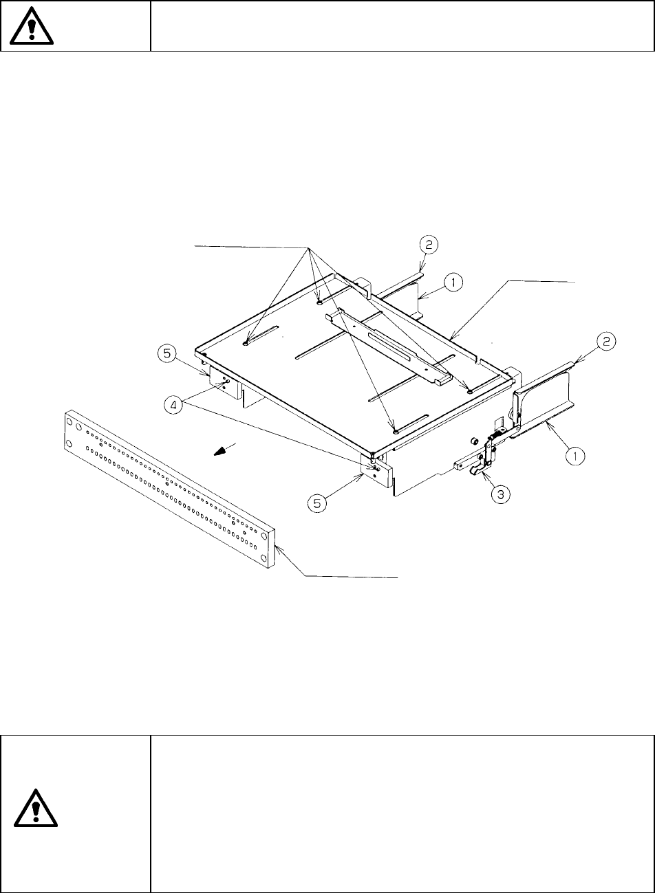
1) Grip the side plate ① and lock lever ② to open the lock holder ③.
2) Insert the front pin ④ into the fixing plate of the rear bank.
3) Release the side plate ① and lock lever ② when the front plate ⑤ into which
the pin ④ is inserted is in contact with the fixing plate, then lock these plates
with the lock holder ③.
4) To detach the matrix tray holder, follow this procedure in the reverse order.
① Side plate
② Tray lock lever
③ Lock holder
④ Pin
⑤ Front plate
Figure 13.4.1
CAUTION
To prevent your body from injury and to avoid damage to the machine,
mount a tray on the matrix tray holder only after you remove the matrix tray
holder from the feeder bank or after you check to see if the main unit
completely stops.
If you mount a tray on the matrix tray holder although the matrix tray holder
is being installed on the feeder bank, be sure to check your environment
before mounting a tray so that the machine cannot start unexpectedly
when another operator operates the machine by mistake.
Top plate
Fixing plate
M3 Hexagonal-hole-headed bolts (four)
13 − 6
13.5 Handling the Bad Mark Sensor
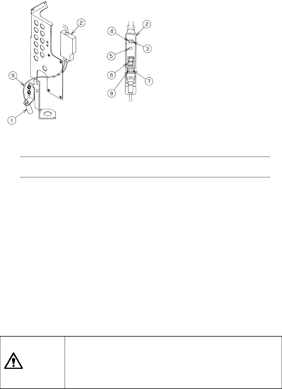
Figure 13.5.1
Note: Do not change the setting of the L-ON/D-ON switch (setting at the factory:
D-ON).
1) Color and size of a bad mark
a) A bad mark on a PC board to which green resist is applied shall be a glossy
white mark of 2.5 mm in diameter or greater.
b) A bad mark on a white ceramic PC board shall be a black mark of 2.5 mm in
diameter or greater.
c) The bad-mark reader cannot recognize the smaller or faded marks. The bad
marks shall be clear and legible.
2) How to set the sensitivity of the bad mark sensor
− Since the sensitivity of the bad mark sensor is set at the factory, do not touch
the mode switch or tuning button easily.
− The bad mark sensor cannot detect a bad mark easily depending on the color
of a board or mark. In such a case, set the sensitivity of the bad mark sensor
as described in the following procedure.
CAUTION
To avoid risk of injury, set the sensitivity of the bad mark sensor only after
you open the cover, and check to see if the main unit comes to halt
completely.
Be carefully to attach the bad mark sensor on the machine so that any
wrong operation of a person working an internal part cannot cause the
machine to start up unexpectedly.
① Detecting head
② Bad mark sensor amplifier
③ Mode switch
④ L-ON/D-ON switch
(decides whether the sensor is
turned ON when receiving light or
when shutting light).
⑤Auto tuning button
⑥Digital display
⑦Stability light (green)
⑧Operation light (red)
⑨Fiber