KJ-01.02.Instruction Manual.REV.02.pdf - 第347页
11 − 1 Chapter 11 PRINTING 11.1 Overview of Printing Operations 11.1.1 Printing This section describes pr eparations necessary f or output ting data such as a production prog ram to a pr inter . ① Connect a printer cable…
10 − 21
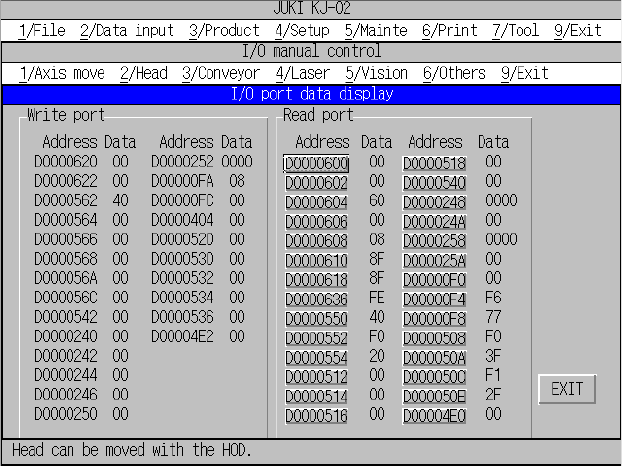
10.4.6.4 I/O port data display
When you select the [6/Others] command on the menu bar, and then the [9/I/O
port data display] command on the displayed menu, the dialog box for displaying
the I/O port data appears on the screen as shown in Figure 10.4.6.4.1.
Figure 10.4.6.4.1 “I/O port data display” dialog box
“Write port” data shows data written to the port until you open the “I/O port data
display” dialog box.
“Read port” data accesses (that is, read) data in real time and displays it.
Addresses under “Read port” function as a button. When you select a <port
address> button, you can select the read access (toggled).
“**” appears at the port data not accessed (read).
11 − 1
Chapter 11 PRINTING
11.1 Overview of Printing Operations
11.1.1 Printing
This section describes preparations necessary for outputting data such as a
production program to a printer.
① Connect a printer cable to the machine and a printer.
② Printers available to this machine are limited to Centronics-compatible and
ESC/P type printers.
③ Since a serial printer does not have any mechanism for detecting a TOF (Top of
Form) generally, adjust the initial printing paper position before power-on
manually.
11.1.2 List of printable data
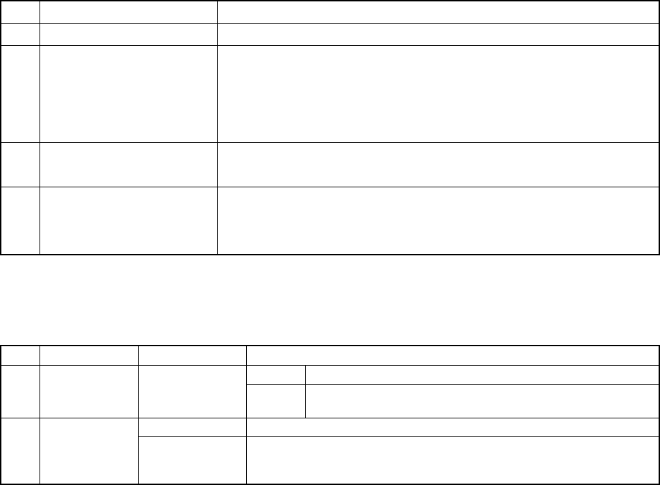
Table 11.1.2.1 lists the printable data.
Table 11.1.2.1 List of the printable data
No. Printing command Description
1 Data file list Prints the list of production programs stored under the specified directory.
2 Production data Prints production programs stored in the current memory:
− PWB data list
− Placement data list
− Component data list
− Pick data list
− Vision data list
3 Setup Prints the current setup data list.
− Machine setup settings and optional unit system
4 Production info Prints the production information stored in the current memory.
− Production information list
− Component information list
− Number of components list
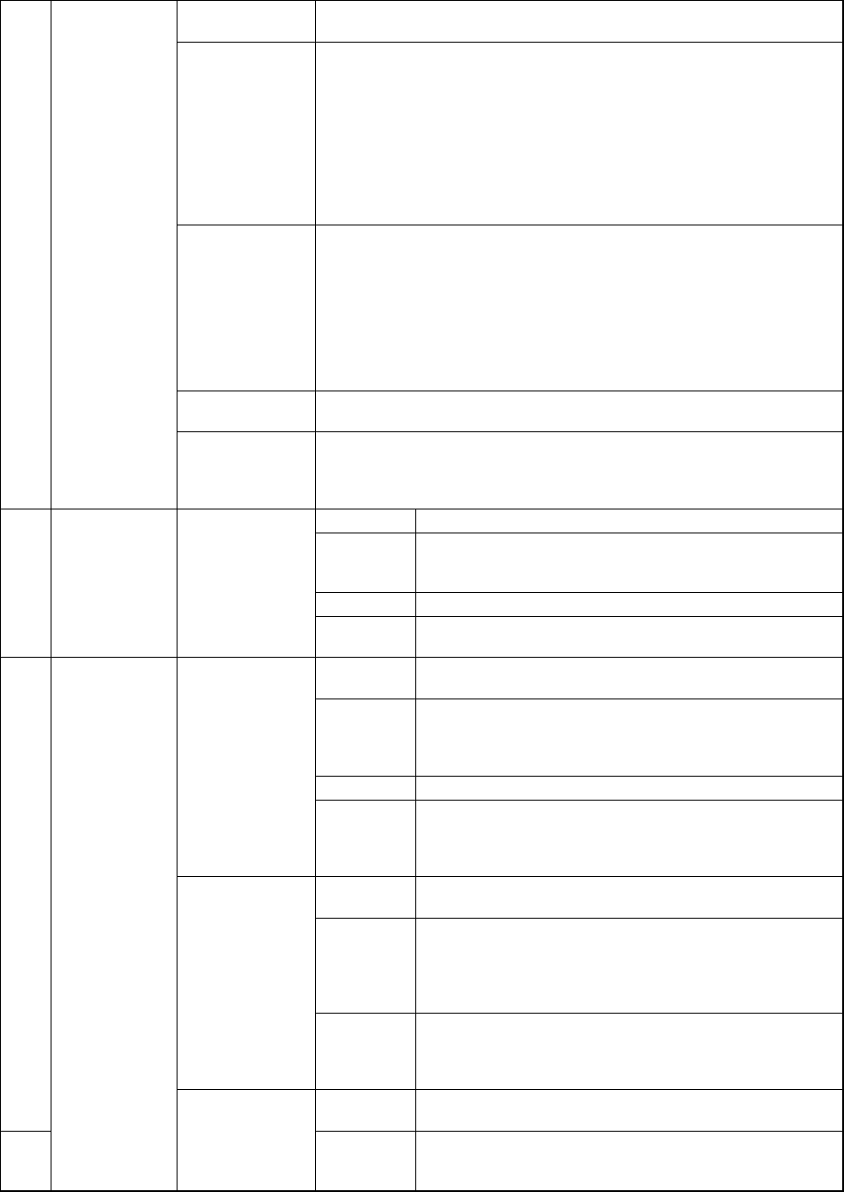
Table 11.1.2.2 shows the data actually printed.
Table 11.1.2.2 Data to be printed
No. Major key Minor key Data to be printed
Header Title, printing date/time, and page 1 Data file list
Data No., production program name, last update date, number of
placement steps, and PWB ID
Common header Title, printing date/time, page, production program name, and PWB ID 2 Production
data
PWB data Reference, PWB configuration, BOC type, Bad mark type, PWB
Reference, Circuit division number, Circuit pitch, BOC mark position,
Bad mark position, PWB height and Circuit position.
11 − 2
Placement data No., Component ID, Placement position (X, Y), Angle, Component
name, Mark information, Skip, Try and Layer. *1
Component data
(on components
centered with
laser)
No., Component name, Comment, Compo. package, Type, Component
width, Component length, Component height, Nozzle No., Vacuum
level, Centering method, Retry times, Placing stroke, Picking stroke,
Trial, Release check, XY speed, Picking Z down, Picking Z up, Placing
Z down, Placing Z up, Theta speed, Compo. aband. (Component
abandonment), Placing offset, Laser position, Laser algorithm,
Tombstone det. (detection), Acceptable values (Width, length, height) ,
Dimension check, Std. (standard) size, W. Judge (width judgment
value), L. Judge (Length judgment value) and packaging setting items.
*2
Component data
(on components
centered with
the VCS)
No., Component name, Comment, Compo. package, Type, Component
width, Component length, Component height, Nozzle No., Vacuum
level, Centering method, Retry times, Placing stroke, Picking stroke,
Trial, Picking depth, XY speed, Picking Z down, Picking Z up, Placing Z
down, Placing Z up, Theta speed, Compo. aband. (Component
abandonment), Placing offset, Recong. Offset (recognition offset),
Dimension check, Std. (standard) size, W. Judge (width judgment
value), L. Judge (Length judgment value) and packaging setting items.
*2
Pick data No., Component name, Pack, Type, Use, Pick, Side, No., Angle and
Picking-up position
2 Production
data
Vision data No., Component Name, Comment, Component Type, Dimension X and
Y, Pitch, Bend, Vision, Lead Length and Width, Lead num. (number of
pins), Miss1 to 3 (information on missing leads), and Vision recog. Ptn
(vision recognition pattern).
Header Title, printing date/time, and page
Machine
setup
ATC nozzle setup, No nozzle vacuum, Installed options,
Reference pin position, Shape clamp position,
Component scrap position and PWB detect sensor.
Unit Length and Pressure
3 Setup
Opn. option Setting of the menu item “Align placement position with
BOC”
Header Title, Printing date/time, page, Production program name,
and PWB ID
Production
conditions
Prod. PWB num. (Plan) (number of PWBs planned to be
produced), Results, Exec. mode (Execution mode),
Placement ofs. (offset), Step No., and Starting pos.
(production start position)
Option Setting of the operation options
Production info
Production
mode
(Total)
Num. (number) of PWBs produced, Production start time,
Running time, Stop time, Num.of components picked,
Num. of components placed and Detection num. of Bad
mark.
Header Title, Printing date/time, page, Production program name,
and PWB ID
Feeder Sply (Supply), No., Component name, Tape width, Type,
Num. of components picked, Num. of components
placed, Number of pick-up errors, Number of retry-over
errors, Recognition, Centering, Tombstone check, and
Verify.
Component
information
Tray Sply (Supply), No., Component name, Num. of
components picked, Num. of components placed,
Number of retry-over errors, Recognition, Centering,
Tombstone check, and Verify
4
Header Title, Printing date/time, Page, Production program name,
and PWB ID
Production info
Parts Num. set
up
Data (on a
tray only)
Pack (package style), No., Component name, Init. (Initial
value), Remain (Number of PWBs not produced), and
Level.