KJ-01.02.Instruction Manual.REV.02.pdf - 第76页
4 − 5 Figure 4.3.2 Machine setup initial screen (2) Figure 4.3.3 Machine setup initial screen (3) Current setting for [Installed options] Current setting for [Reference pin position], [Shape clamp position], and [Compone…
4 − 4
4.3 Machine Setup
The following table shows the machine setup items.
Table 4.3.1 Machine setup items
No. Machine setup group Description
1 ATC nozzle setup Assign nozzles to A to R of ATC.
Set also the vacuum value for each nozzle when it is installed in the head.
Set also the laser measurement height offset for each nozzle when it is
installed inthe head.
2 Vacuum value without
nozzle
Vacuum value when the nozzle is not mounted.
3 Device enable If a device unit is defined as “not used” by this setup parameter, a production
run is completed normally even when that device unit is indispensable to the
production of the boards.
Example: If the upright chip sensor is defined as “not used” by this parameter,
no upright chip detection is made to complete the placement procedure even if
upright chip detection is commanded in the production program.
4 Reference pin position Positions of the reference and follower pins from the origin.
5 Shape clamp position Position of the edge reference from the origin.
6 Component scrap
position
The position where IC components are discarded.
The position where chip components are discarded.
7 IC conveyor belt
position
The position where the IC collection belt is installed.
The position on the IC collection belt where the components are discarded.
8 PWB conveyor Set the delay time of the PWB transport sensor (delay time of the PWB
transport sensor for a board with a cutout or hole) and that of the shape
reference Y-clamp (whether to delay the Y clamp operation or not).
9 Signal light Setting of the signal light pattern for each operation phase
10 Nozzle data
installation
Add a nozzle to be used.
11 Exit Ends the machine setup procedure.
(1) Immediately after start-up
The machine setup initial screen, as shown in Figure 4.3.1 through Figure 4.3.4,
appears when [4/ Setup] and then [3/ Machine setup] is selected from the menu bar.
The machine setup initial screen shows the values defined currently for the
parameters to be set. To scroll the screen, move the scroll bar up and down using
the cursor keys or page up and down keys.
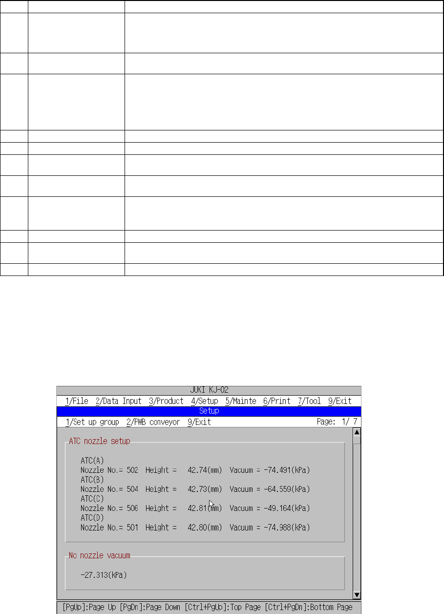
Figure 4.3.1 Machine setup initial screen (1)
Current setting for
[ATC nozzle setup], and
[Vacuum value without
nozzle],
4 − 5
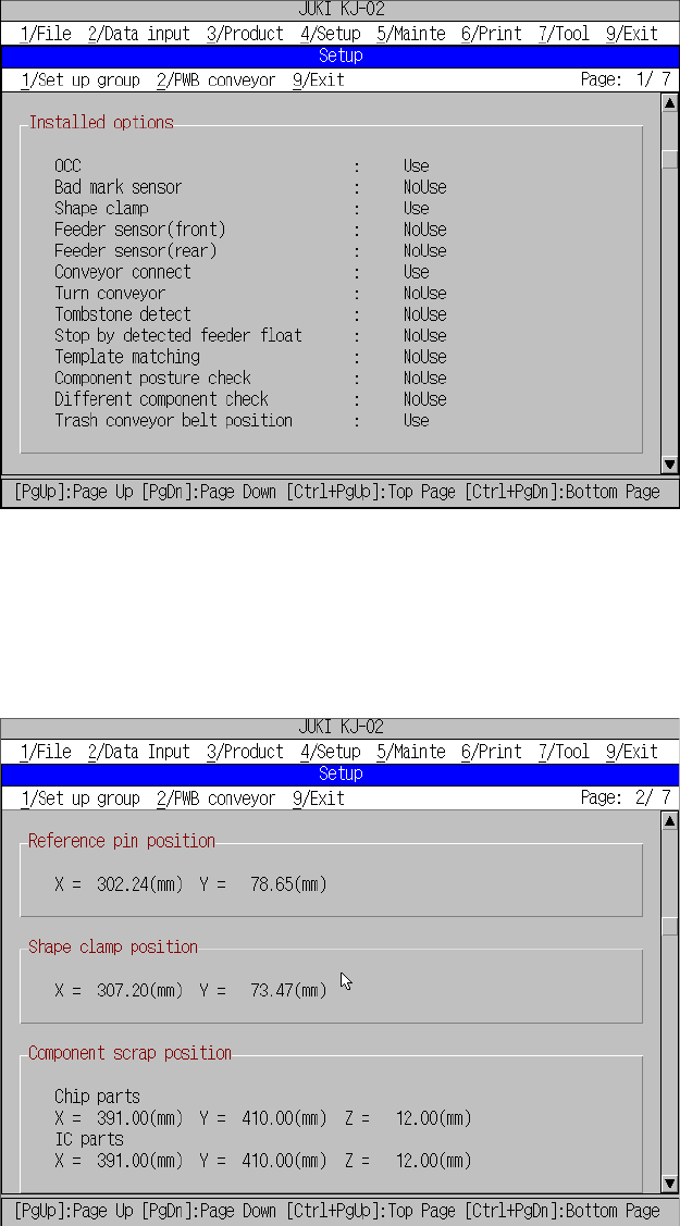
Figure 4.3.2 Machine setup initial screen (2)
Figure 4.3.3 Machine setup initial screen (3)
Current setting for
[Installed options]
Current setting for
[Reference pin position],
[Shape clamp position],
and [Component scrap
position],
4 − 6
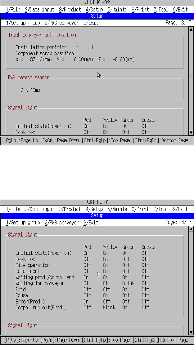
Figure 4.3.4 Machine setup initial screen (4)
Figure 4.3.5 Machine setup initial screen (5)
Current setting for
[Trash conveyor belt
position], [PWB detect
sensor].
Current setting for
[Signal light].