KJ-01.02.Instruction Manual.REV.02.pdf - 第282页
8 − 15 8.2.1 PC board production Select [3/ Pr od.] in t he menu bar . The screen appear s and the Producing condition setting dialog box is displayed. Figure 8.2. 1.1 shows the Production star ting scr een ("Produc…
8 − 14
(2) Production mode
There are three types of production modes.
Table 8.2.1 Production modes
No. Production mode Description
1 Board production
mode
Determines the number of PC boards on which components are placed, and
actually places components on the PC board.
2 Trial run mode Test-places a preset number of components on a PC board, check the status
of placement of components on the PC board. In case the placement is
found not satisfactory by the camera tracking function, teaching can be
performed.
3 Blank run mode Test-runs the machine without using component. This mode is used to check
the pickup and placing operations of the machine
Each of the above operations can have its operating conditions (production
condition, test-run condition, or blank-run condition).
(3) Execution modes
Each production mode has two kinds of execution modes.
Table 8.2.2 Execution modes
No. Execution mode Description
1 Continuous Keep on placing components on PC boards until the specified production
ends or the production is terminated by pressing the STOP button in Pause
mode.
2 Step Pauses production at the end of every production step.
The pause positions are as follows:
1) After reaching the pickup position
2) After reaching the placing position
3) After reaching the bad-mark position
4) After reaching the fiducial position
5) After reaching to the VCS recognition position
To restart the production, press the START key.
Note: The STOP key is also available in the CONTINUOUS mode. When the STOP
key pressed, the machine pauses at the end of the current production step (at
the pause position).
8 − 15
8.2.1 PC board production
Select [3/ Prod.] in the menu bar. The screen appears and the Producing condition
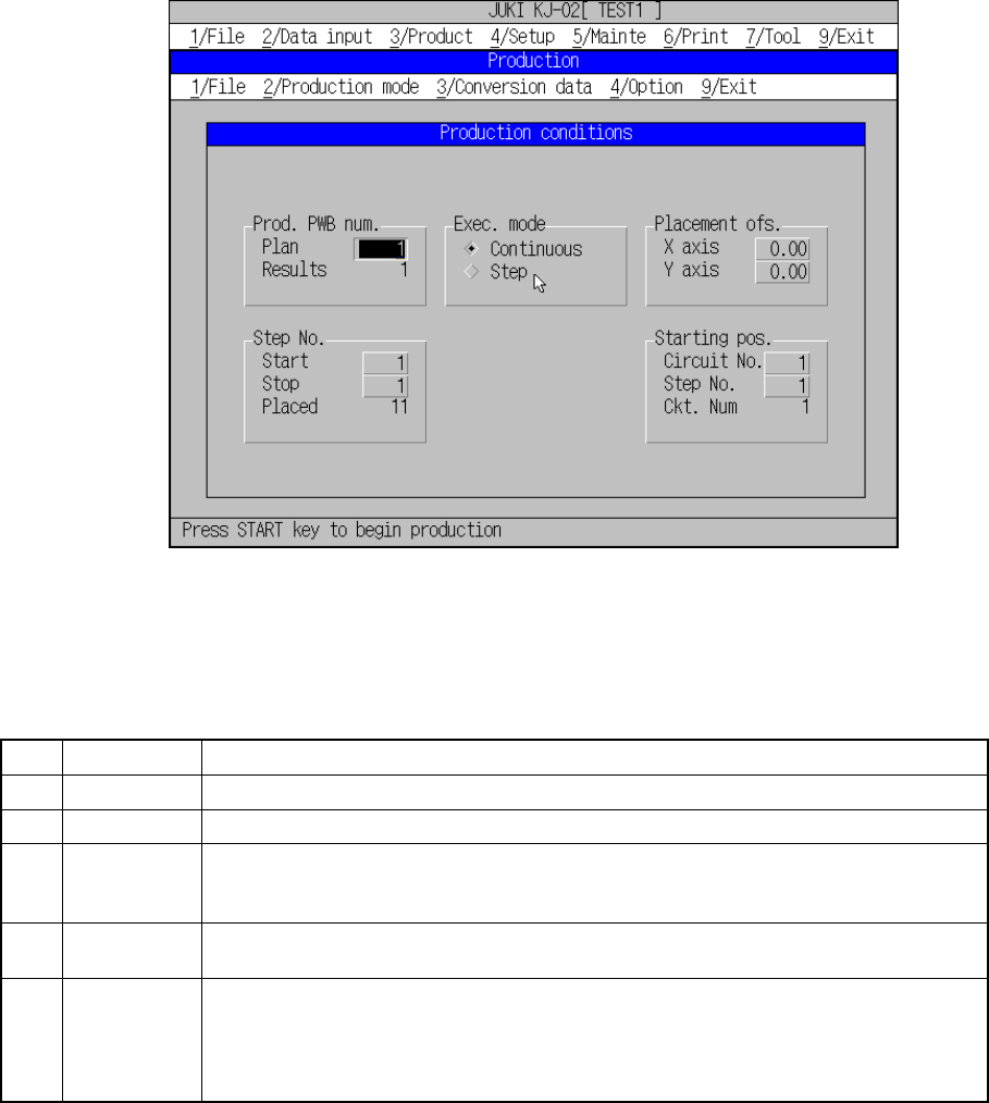
setting dialog box is displayed. Figure 8.2.1.1 shows the Production starting screen
("Production conditions" setting dialog box.).
Figure 8.2.1.1 Production starting screen
8.2.1.1 Production conditions
(1) Setting items
No. Item Description
1 Prod. PWB Set the number of boards to be produced.
3 Exec. mode Select either "Continuous" or "Step" execution mode.
4 Step No. Specify a range of placement data with the placement start line and the placement end
line.
Specify the data in the order of "Input order".
5 Placement
ofs.
Specify total offsets for all placement positions. This adds the set offset to the placement
data for actual placement.
6 Starting pos. For the first production board only, specify the circuit and placement number where the
first placement is performed. If, for some reason, board production on the machine is put
in a halt, this setting continues the production.
This is effective to place the remaining components on the board to which placement
was put in a halt.
8 − 16
(2) Operation
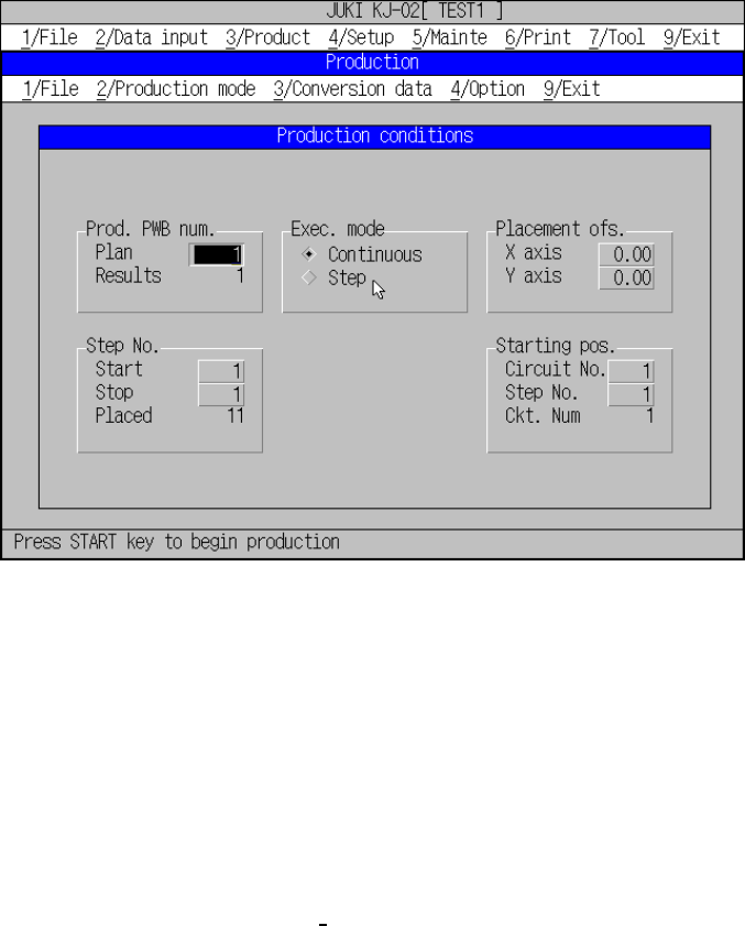
Figure 8.2.1.2 shows the initial screen to set conditions for production.
Figure 8.2.1.2 Production condition initial screen
① Prod. PWB
Enter the number of PC boards on which components are to be placed in
the “Plan” field.
The number of boards already processed is reset to 0 when the Production
screen is displayed.
Normally, the preset number of PC boards for “Plan” and “Results” are set
in their initial statuses. When the item “Accumulated the number of boards
produced” is checked on the
“Operation option (Production (Display))”
screen, those number of “Plan” and that of “Results” are those of the
previous production. If, in this status, production is started, counting of the
board starts from the previous result number and the production continues
until the number of production boards reaches the number set as “Rerults”.
If a new number of boards is set for the Plan, and the number of boards is
cleared to zero for the “Results”, the board production can be started
newly.
② Exec. mode
Select either “Continuous” or “Step” execution mode and press the radio
button for it.
③ Step No.
Enter the placement start line and the placement end line in the “Start” and
“Stop” fields to set a range of placement. The “Placed” field displays the
number of components to be placed. These fields display initial values.