KJ-01.02.Instruction Manual.REV.02.pdf - 第160页
5 − 64 ④ Tray thic k Enter the height “T” fr om the bot tom of the tr ay to the surf ace including t he component itself . Figure 5.5.1. 16 Figure of T ray thickness T T Case 1 Case 2 Component Tray
5 − 63
<3> Working on the “Tray” window
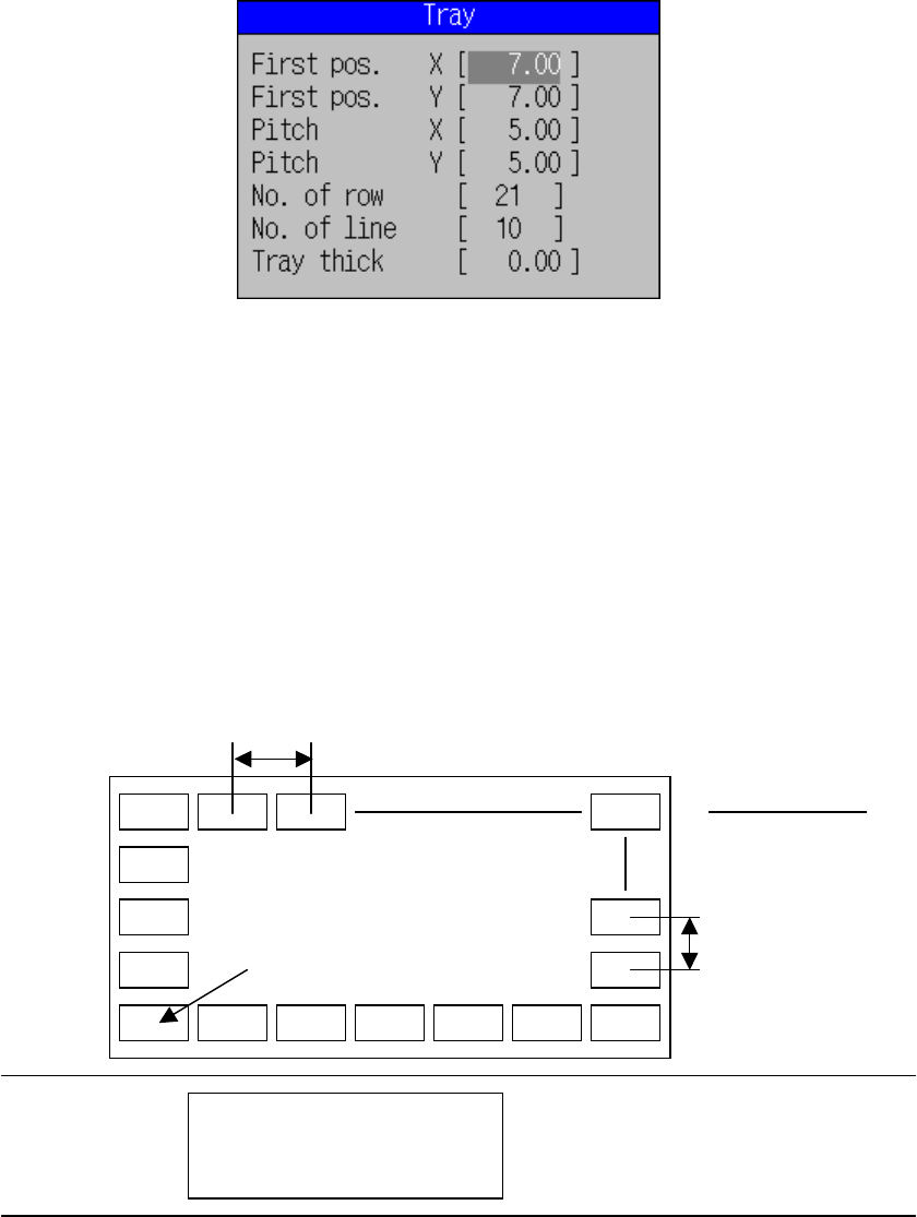
The window for tray setting is shown in Figure 5.5.1.14.
Figure 5.5.1.14 Tray setting dialog box
① First pos. (position)
Enter the center position (X and Y) of the first component on the tray,
measured from the edge of the tray.
② Pitch
Enter the pitches (pitches X and Y) between components.
③ No. of row and line (number of components)
Enter the number of components (Xn, Yn) in horizontal and vertical
directions.
Figure 5.5.1.15 Figure of First component position, pitch,
and the number of components
Yn
Xn
Tray holder
Pitch Y
First component position
Board Transport path

5 − 64
④ Tray thick
Enter the height “T” from the bottom of the tray to the surface including the
component itself.
Figure 5.5.1.16 Figure of Tray thickness
T
T
Case 1
Case 2
Component Tray
5 − 65
<6> Working on the expanded windows
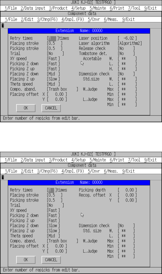
The extension window displayed when the centering method is set to “Laser
algorithm” is shown in Figure 5.5.1.17, and that set to “VCS” is shown in Figure
5.5.1.18.
Figure 5.5.1.17 Expanded window for laser centering
Figure 5.5.1.18 Expanded window for vision centering