KJ-01.02.Instruction Manual.REV.02.pdf - 第374页
14 − 5 14.2.4 A ir filter ( Head) 1) Loosen the screw ② fixing t he Z slide shaft ① to pull out t he nozzle outer shaft ③ . 2) Check to see if ther e is any contamination of the f ilter ④ . 3) If any , rem ove the filt e…
14 − 4
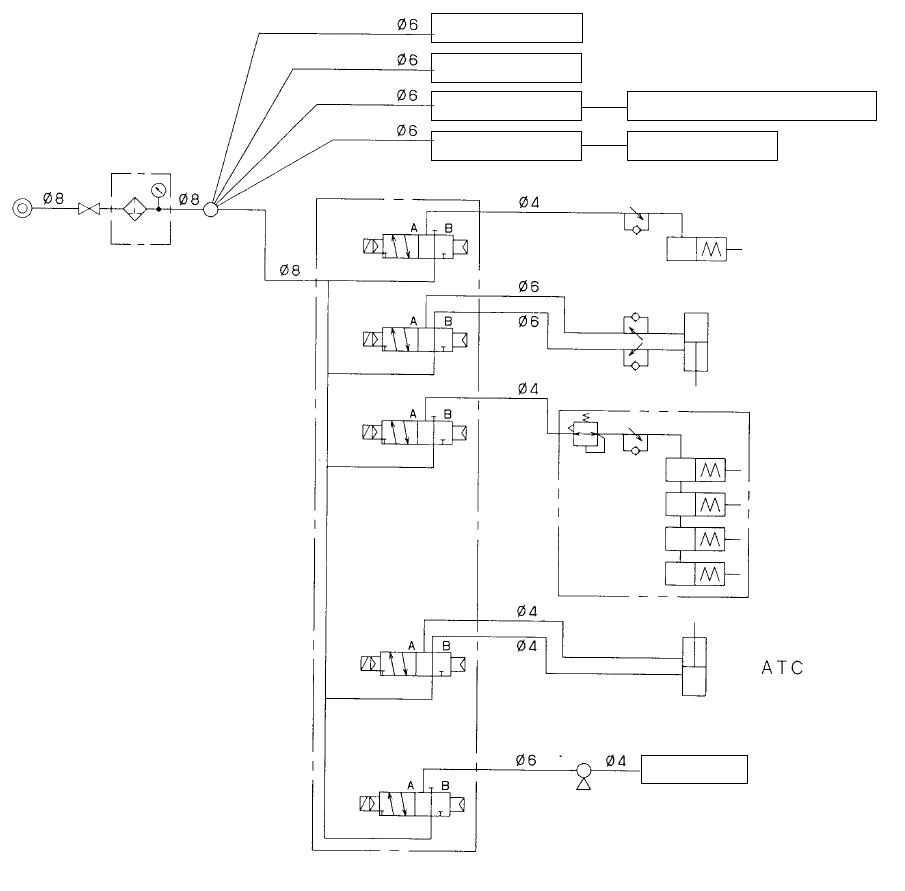
See the piping diagram shown below as the reference material.
(Filter regulator)
Drive c
y
linder F
Drive c
y
linder R
Female union 32-mm adhesive ta
p
e feeder
E
j
ector unit IC Z-slide bracket
Stopper
Support
(optional)
pusher Y (X4)
(Ejector)
CAL block
(optional)
(Electromagnetic valve)
14 − 5
14.2.4 Air filter (Head)
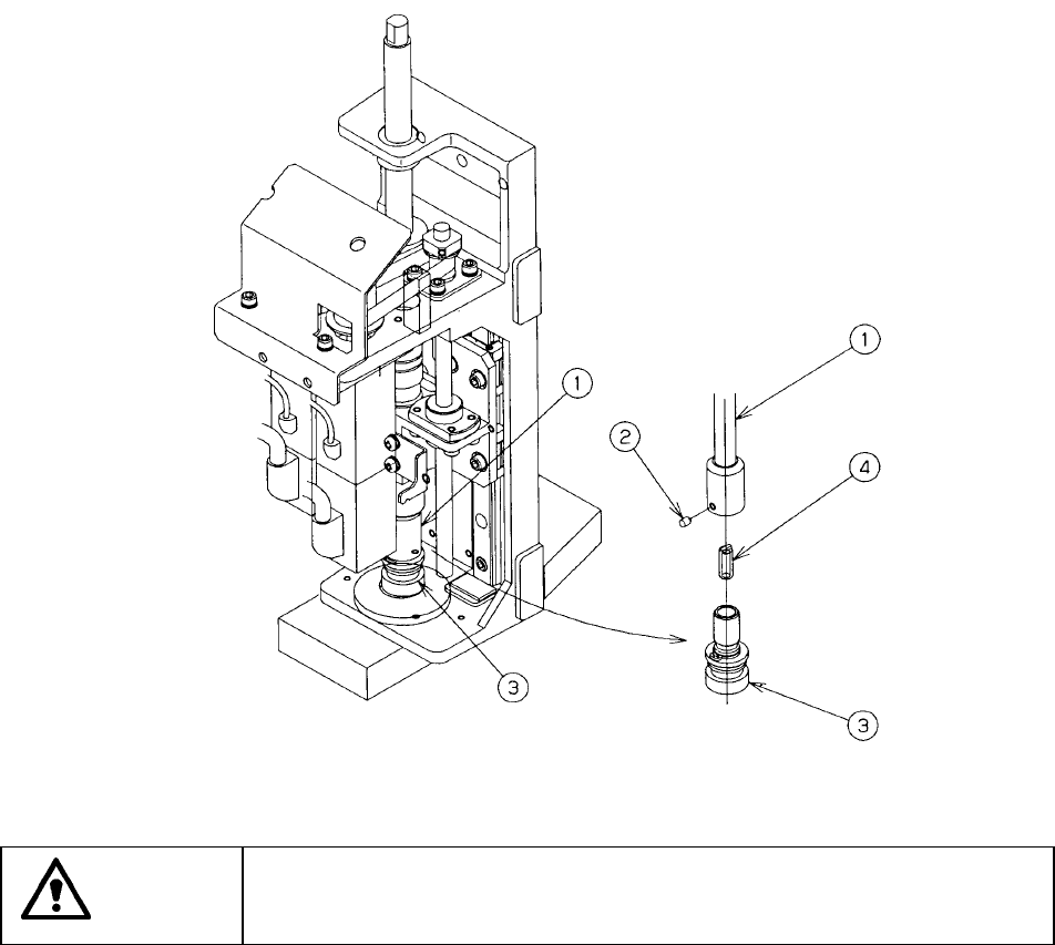
1) Loosen the screw ② fixing the Z slide shaft ① to pull out the nozzle outer
shaft ③.
2) Check to see if there is any contamination of the filter ④.
3) If any, remove the filter ④ from the nozzle outer shaft, the replace it with a new
one.
4) Push the nozzle outer shaft ③ into the Z slide shaft ①, then fix it with the
screw ②.
Filter ④: Part number E3014727000
CAUTION
To prevent the body from injury which can be caused by accidental
activation of the machine, turn off the power of the machine before
following the operation above.
14 − 6
14.2.5 Transport belt
Check that the belt is severely worn-out, damaged, or stretched. If it is necessary
to replace the belt, follow the procedure below.
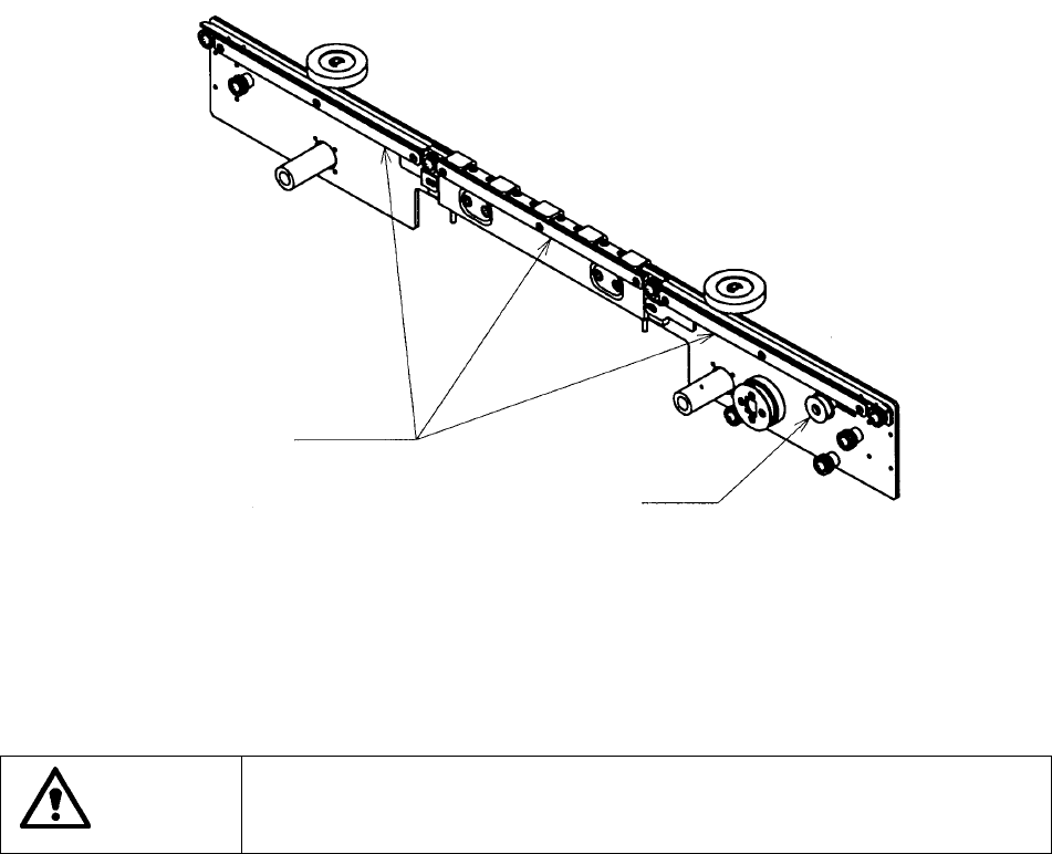
1) Loosen all screw and nut of the transport pulley as shown in Figure 13.2.5.1 to
loosen tension of the belt.
2) Loosen the flush bolts of the PWB transport belt as shown in Figure 13.2.5.1 to
remove the PWB transport belt guides. At this point, you can remove/attach
the PWB transport belt.
Figure 14.2.5.1
CAUTION
To prevent the body from injury which can be caused by accidental
activation of the machine, turn off the power of the machine before
following the operation above.
PWB transport belt guides
Transport pulley