KJ-01.02.Instruction Manual.REV.02.pdf - 第47页
1 − 31 (4) ⑤ is a DSUB 25-pin connector for a printer conf or ming to t he Centeronics Interf ace standards. (5) ⑥ is a connector f or an opt ional track ball. (6) ⑦ is a connector f or a k eyboard. (7) ⑧ is an air coupl…
1 − 30
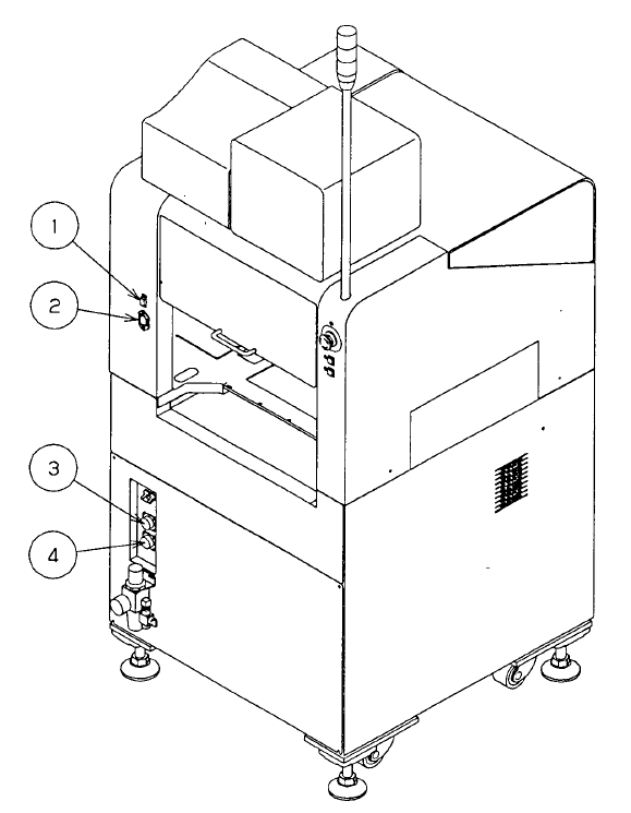
1.4 Interface With Extenal Devices
(1) ① is a 15-pin connector for a CRT.
(2) ② is a 3-pin power connector for a CRT (100V AC).
(3) ③ is a 14-pin READY IN connector, and 4 is the 14-pin READY OUT connector:
both are to be used when the machine is configured with other equipment in an
on-line environment.
Figure 1.4.1
1 − 31
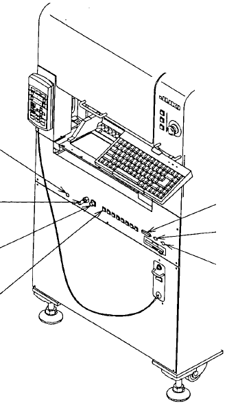
(4) ⑤ is a DSUB 25-pin connector for a printer conforming to the Centeronics
Interface standards.
(5) ⑥ is a connector for an optional trackball.
(6) ⑦ is a connector for a keyboard.
(7) ⑧ is an air coupling for a CAL block.
(8) ⑨ is a female union for a 32-mm adhesive tape feeder.
(9) ⑩ is a 6-pin ALARM signal connector for an optional IC trash belt.
(10) ⑪ is a 12-pin power connector for an optional IC trash belt or 32-mm adhesive
paper tape feeder. Eight connectors of the same type are located on the front of
the machine.
Figure 1.4.2
⑧
⑨
⑩
⑪
⑤
⑥
⑦
1 − 32
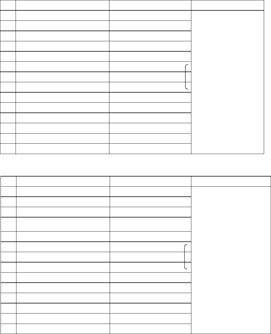
Table 1-4-1 List of connectors on the left side panel
Signal name (left to right) Signal name (right to left) Connector used
1 READY OUT + READY IN +
2 READY OUT - READY IN - (GND)
3 BOAD AVAILABLE IN + BOAD AVAILABLE OUT +
4 BOAD AVAILABLE IN - (GND) BOAD AVAILABLE OUT -
5 N.C. N.C.
6 N.C. N.C.
7 N.C. N.C.
8 N.C. N.C.
9 N.C. N.C.
10 N.C. N.C.
11 N.C. N.C.
12 N.C. N.C.
13 N.C. N.C.
14 N.C. N.C.
Table 1-4-2 List of connectors on the right side panel
Signal name (left to right) Signal name (right to left) Connector used
1
READY IN + READY OUT +
2
READY IN - (GND) READY OUT -
3
BOAD AVAILABLE OUT + BOAD AVAILABLE IN +
4
BOAD AVAILABLE OUT - BOAD AVAILABLE IN -
(GND)
5
N.C. N.C.
6
N.C. N.C.
7
N.C. N.C.
8
N.C. N.C.
9
N.C. N.C.
10
N.C. N.C.
11
N.C. N.C.
12
N.C. N.C.
13
N.C. N.C.
14
N.C. N.C.
(Connection of the
cable end 206044-1)
AMP
206043-1
(Connection of the
cable end 206044-1)
AMP
206043-1