KJ-01.02.Instruction Manual.REV.02.pdf - 第231页
6 − 27 6.4.3 Recognition component examples The component s to be supported by the component outline recog nition f unction are those whose shapes are close to a rectang le or reg ular squar e. The edges f orm ing an out…
6 − 26
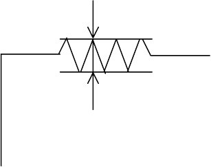
⑥ Components whose side roughness forming a linear portion is 0.1 mm or
less
Fig. 6.4.2.7 Explanatory Drawing of Recognition Condition ⑥
⑦ Components whose component shape is not convex.
When the above conditions are satisfied, side recognition is enabled.
(3) Center recognition
Recognition conditions
① Components whose ratio of width to length is 1:2 or more
② Components whose side portion is 0.3 mm or more (The inside of a side
may be hollow at imaging.)
When the above conditions are satisfied, center recognition is enabled.
Note: Concavity and convexity may exit on the component outline. However,
they have an effect on the center position and inclination.
In this case, adjust the placement data, etc.
0.1 mm or less
6 − 27
6.4.3 Recognition component examples
The components to be supported by the component outline recognition function are
those whose shapes are close to a rectangle or regular square.
The edges forming an outline should be 0.3 mm or more.
Black components cannot be recognized.
The machine can recognize the center of a component if the length of its longer side
is twice or more the length of its shorter side.
In the component drawing shown in the following table, the black/white is reversed
unlike the reality.
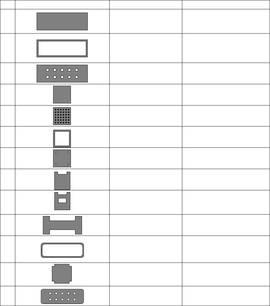
Table 6.4.3.1 Recognition Components Table
No. Recognition component shape Recognition method Remarks
1 Center recognition (Note)
Side recognition
Corner recognition
Rectangular component
2 Center recognition (Note)
Side recognition
Corner recognition
The inside of the component is
hollow.
Outline edge should be 0.3 mm or
more.
3 Center recognition (Note)
Side recognition
Corner recognition
The inside of the component is
undefined.
4
Side recognition
Corner recognition
Square component
5 Side recognition
Corner recognition
CBGA
6 Side recognition
Corner recognition
The inside of the component is
hollow.
7 Side recognition
Corner recognition
The inside of the component is
hollow.
8 Corner recognition The side shape is concave.
9
Corner recognition The side shape is concave.
The inside of the component is
undefined.
10 Corner recognition
Center recognition (Note)
The side shape is concave.
However, only components of
point symmetry.
11 Side recognition
Center recognition (Note)
The inside of the component is
hollow.
The outline edge should be 0.3
mm or more.
12
Side recognition
Missing corner
13 Side recognition
Center recognition (Note)
Missing corner. The inside shape
is undefined.
Note: Center recognition is enabled when the longer side is twice or more as long as the
shorter side.
6 − 28
6.5
Setting the Vision Recognition Pattern for a BGA/FBGA
Component
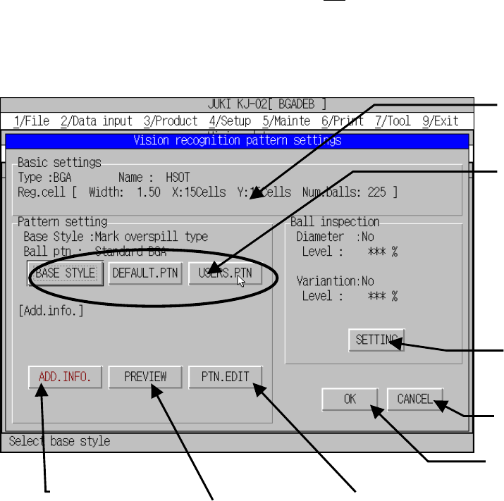
6.5.1 “Vision recognition pattern settings” dialog box (BGA/FBGA)
On this dialog box, set the parameter for the recognition pattern used for a BGA or
FBGA component. When you click the <OK
> switch on the Vision data screen, the
machine displays this dialog box. See Table 6.5.1.1 for each item displayed on this
dialog box.
Figure 6.5.1.1 Explanations of the dialog box
Basic settings
Display the basic settings of
the recognition data. This
data cannot be changed.
Base style
Base style of a BGA bottom
Default selection/Pattern
selection
Specifies the ball pattern
which is incorporated into the
system.
User pattern
Specifies the ball pattern you
created.
Ball inspection setting
Performs various inspection
settings.
Detail
Sets the parameter
unique to each default
pattern.
Preview
Displays the current
pattern in the form of
graphics.
Pattern editing
Performs the user
pattern edition.
Cancels your settings, then
closes this dialog box.
Validates your settings, then
closes this dialog box.