KJ-01.02.Instruction Manual.REV.02.pdf - 第157页
5 − 61 <2> Working on the “T ape” w indow ① T ape width Select t he appropriate t ape width from the pop-up menu. Figure 5.5.1. 1 1 T ape width selection screen ② Feed pit ch Select t he feed pit ch fr om the pop- …
5 − 60
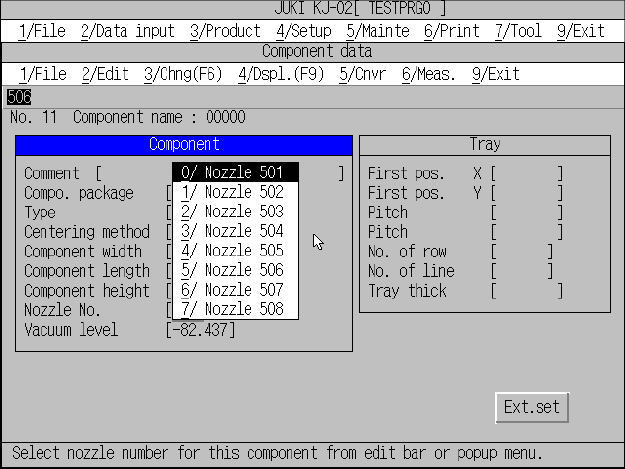
⑥ Nozzle No.
When you enter the component dimensions, the machine automatically sets
the nozzle number. If you want to change this nozzle number because the
machine is not equipped with the nozzle whose number is automatically set,
select an appropriate one from the displayed pop-up menu, or click the
[2/Edit] command and enter one on the displayed menu. When you enter a
nozzle number from the “Edit” menu, you can select a nozzle that is set with
the [Nozzle data installation] command on the Machine setup menu (see
Section 4.3.10 “Nozzle data installation”).
Figure 5.5.1.10 Nozzle no. input screen
⑦ Vacuum level
The vacuum value, when the component is picked with the nozzle
designated by the nozzle number, is displayed. It is not necessary to change
the value.
5 − 61
<2> Working on the “Tape” window
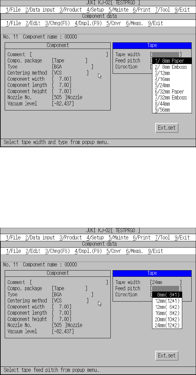
① Tape width
Select the appropriate tape width from the pop-up menu.
Figure 5.5.1.11 Tape width selection screen
② Feed pitch
Select the feed pitch from the pop-up menu.
Each tape width has unique feed pitches to be selected. Note that certain
feed pitches are not selectable for particular tape widths.
Figure 5.5.1.12 Feed pitch selection screen
5 − 62
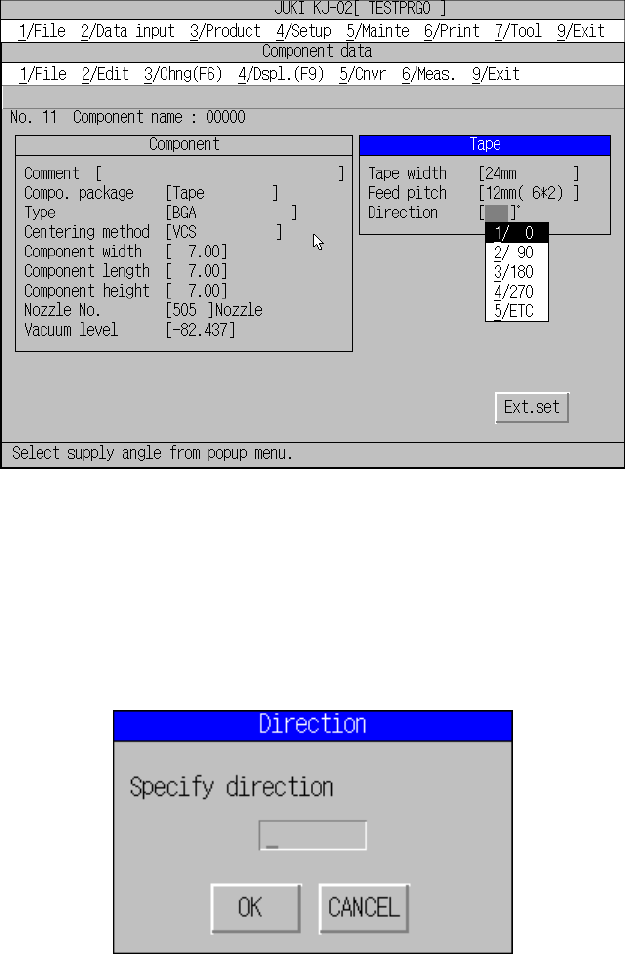
③ Direction (Component feed direction)
Define the angle of component feed according to the lot of the components.
The angle for the usually fed components shall be set to 0 degree. For the
other components with different angles, change only the feed angle.
Placement angle is not necessary to change.
Figure 5.5.1.13 Component feed direction selection screen
When selecting [5/ Other], a pop-up menu for entering placement angle appears.
Enter the desired angle within the range of 0° to 359°.
This feature can be used for the components fed at an angle of 45° such as
GaAsFET.
Direction input dialog box