KJ-01.02.Instruction Manual.REV.02.pdf - 第277页
8 − 10 Figure 8.1.3.9 Figure 8.1.3. 10 W ARNING T o prevent the body from injury that can be caused by accidental activation of the machine, turn of f the power of the machine before startin g to work . (2) Compensat ion…
8 − 9
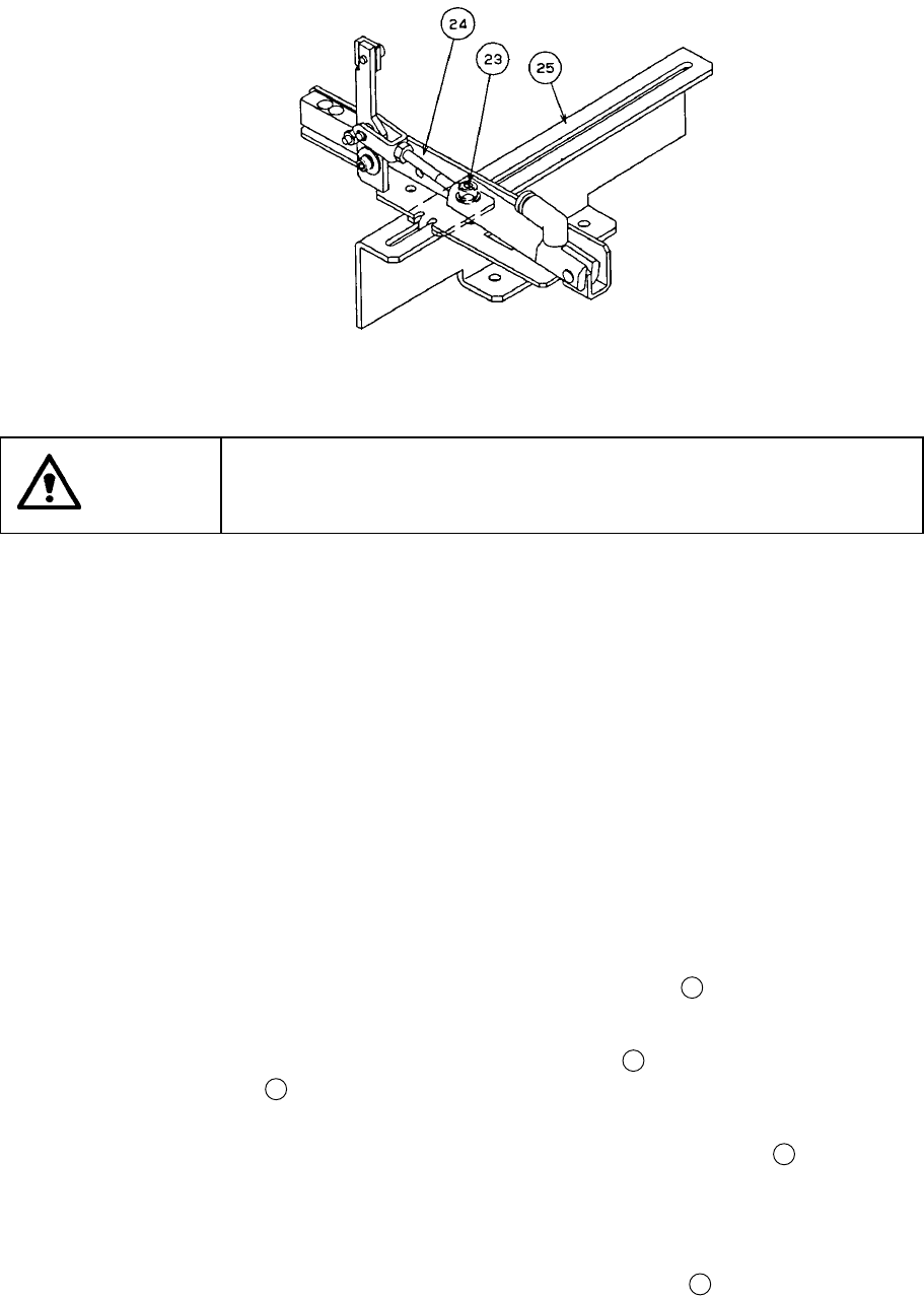
Figure 8.1.3.8
WARNING
To prevent the body from injury that can be caused by accidental
activation of the machine, turn off the power of the machine before
starting to work.
4) The STOP sensor ⑥ operates according to the stopper position since it is
attached on the stopper assembly.
5) When you move the stopper assembly, follow the procedure described
under Section 8.1.3.2 (6) “Entering positions for the use of Board outline
reference” again.
Check to see if the STOP sensor ⑥ is set to ON when you set a board
above the STOP sensor and if it is set to OFF when you remove a board
from it. If the STOP sensor does not operate in this way, adjust the STOP
sensor ⑥ with its control (when the sensor is set to ON, the LED of the
sensor lights in red.)
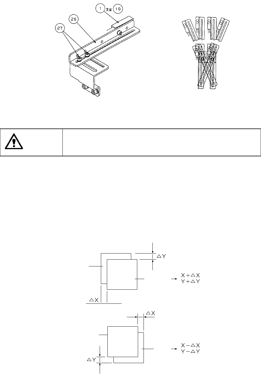
c. PWB detecting sensor (see Figures 8.1.3.9 and 8.1.3.10.)
You can move the IN sensor ① and OUT sensor ⑩ operation positions by
changing the position and angle of the sensor bracket
26
.
1) Turn off the power of the main unit.
2) Loosen the M3 hexagonal-hole-headed bolt
27
that fixes the sensor
bracket
26
. You can move this bolt back and forth, left and right, and
rotate it along the long hole.
3) After adjusting, tighten the M3 hexagonal-hole-headed bolt
27
.
4) Check to see if a board is set with using the [3/Conveyor] command on the
I/O Manual Control menu, [PWB conveyor] command on the “Setup” menu
and [Cnvr] command on each data screen.
5) Check to see if the IN sensor
①
and OUT sensor
27
are set to ON when
you set a board under these sensors, and if they are set to OFF when you
remove a board from these sensors. If theses sensors do not operate in
this way, adjust them with their controls respectively. (When each sensor
is set to ON, its LED lights in red.)
8 − 10
Figure 8.1.3.9 Figure 8.1.3.10
WARNING
To prevent the body from injury that can be caused by accidental
activation of the machine, turn off the power of the machine before
starting to work.
(2) Compensation
Follow the description of Section 7.4 “Trial Production”, test-place components
on a working PWB and check for the deviations between elements and pads.
When detecting any deviation, compensate its X and Y coordinates in
"Placement offset" in Production mode.
,
Figure 8.1.3.11
Pad
Pad
Element
Element
8 − 11
CHAPTER 8 PRODUCTION PROCEDURE
8.1 Preparations for Production
8.1.1. Preparations of the component supplying section
8.1.2 Preparations of the ATC
8.1.3 Preparations of the PWB transport section
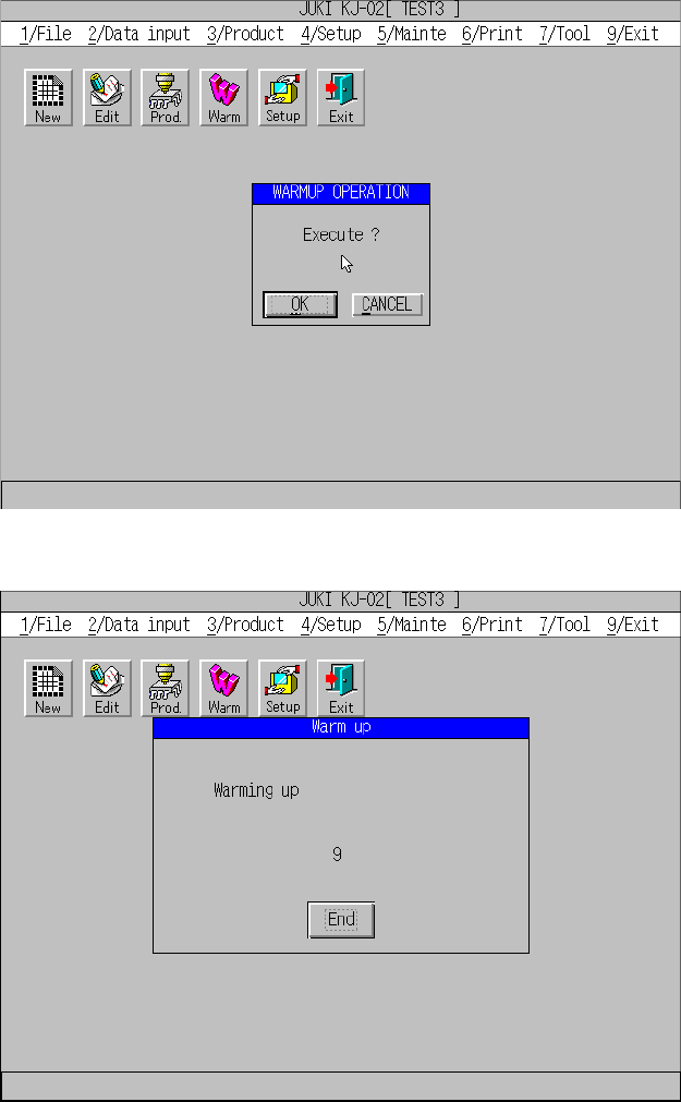
8.1.4 Warming up