KJ-01.02.Instruction Manual.REV.02.pdf - 第43页
1 − 27 1.2.7 OCC parts identificat ion (1) Of fset correction ca mera T he machine is eq uipped with a coaxial light and polarizing f ilter as the standar d devices. T he camera detect s a BOC mar k and corr ects the det…
1 − 26
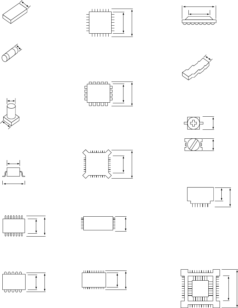
(3) Minimum component width (D) of each component.
!1
A
D
A
D
W
D
A
D = A
A
D
A
D
A
D
A
D
D
A
D = A
A
A
A
D = A
AA
D = A
A
D
A
D
A
D
① Square chip
② MELF
③ Aluminum
electrolytic capacitor
D = A + 0.5mm
④ SOT
⑤ SOP
⑥ SOJ
⑦ QFP ⑫ BGA
⑧ PLCC
⑨ BQFP
⑩ TSOP
⑪ TSOP2
⑬ Network resistor
⑭ Trimmer
⑮ One-way lead connector
⑯ Gull wing socket
J lead socket
Socket with bumper
1 − 27
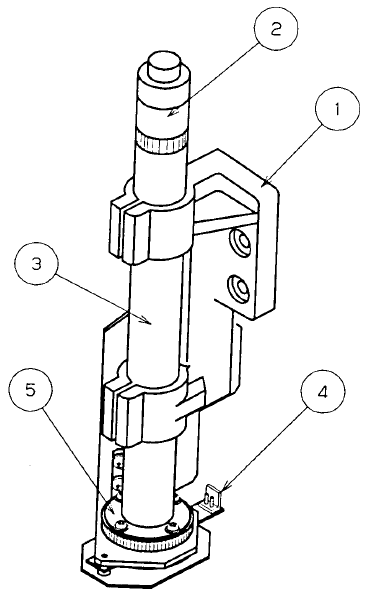
1.2.7 OCC parts identification
(1) Offset correction camera
The machine is equipped with a coaxial light and polarizing filter as the standard
devices. The camera detects a BOC mark and corrects the detected mark
automatically.
① Camera holder
② CCD camera
③ CCD camera lens
④ Illumination LED board
⑤ Polarizing filter
Figure 1.2.7.1
1 − 28
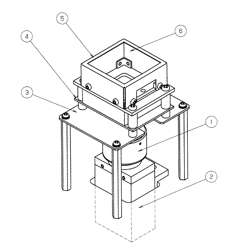
1.2.8 VCS: parts identification (only for a KJ-02)
① VCS lens
② VCS camera
③ Light base
④ Illumination LED board
⑤ CSP diffuser cover
⑥ BGA light LED board
Figure 1.2.8