KJ-01.02.Instruction Manual.REV.02.pdf - 第372页
14 − 3 14.2.2 Piping and joint Check that there is no air leakag e. Check to see if connections indicated with arrow mark s are made securely , and if no air leaks f rom t hese connections. CA UTION T o prevent the body …
14 − 2
14.2 Check
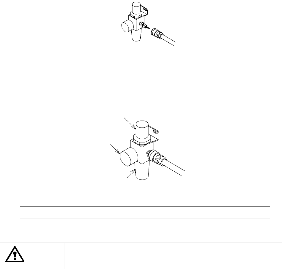
14.2.1 Air pressure
Checking to see if the air pressure is 0.5 Mpa.
How to adjust the air pressure
1) Connect an air hose to the filter regulator to supply the machine with air.
2) Pull up the pressure knob, and turn it around to adjust the air pressure so that it
can be within 0.5 ± 0.05 Mpa.
3) If oil or water is pooled in the drain, exhaust it.
Note: The air pressure is adjusted at the factory. Check the pressure level.
CAUTION
To prevent the body from injury which can be caused by accidental
activation of the machine, turn off the power of the machine before
following the operation above.
Pressure adjustment knob
0.5 ± 0.05 Mpa
Drain
14 − 3
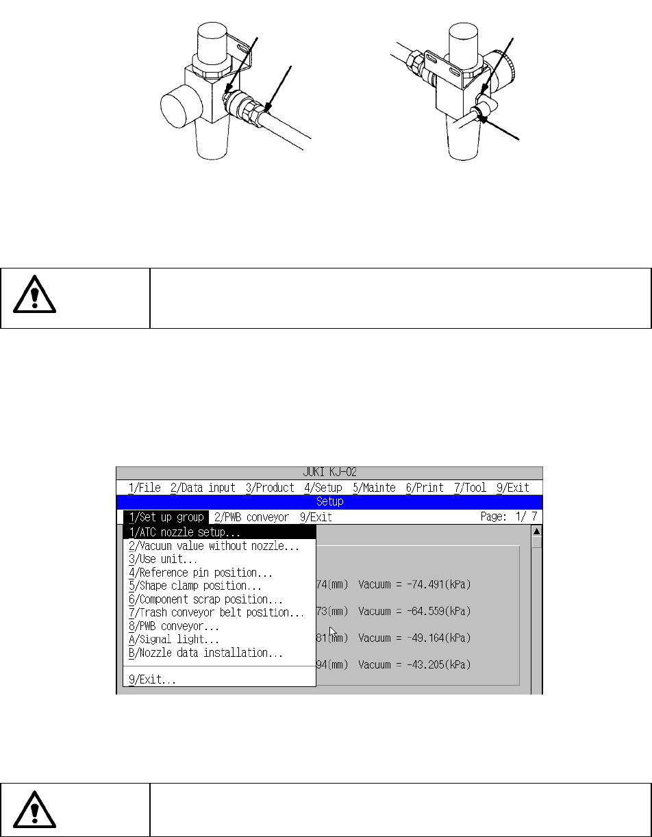
14.2.2 Piping and joint
Check that there is no air leakage.
Check to see if connections indicated with arrow marks are made securely, and
if no air leaks from these connections.
CAUTION
To prevent the body from injury which can be caused by accidental
activation of the machine, turn off the power of the machine before
following the operation above.
14.2.3 Unit air cylinder
Turn on the power of the machine, select the machine setup items, and check that
operation is possible.
Figure Machine setup group pull-down menu
CAUTION
To avoid risk of injury, do not place your hand in the machine, nor move
your face or head close to the machine while it is operating.
14 − 4
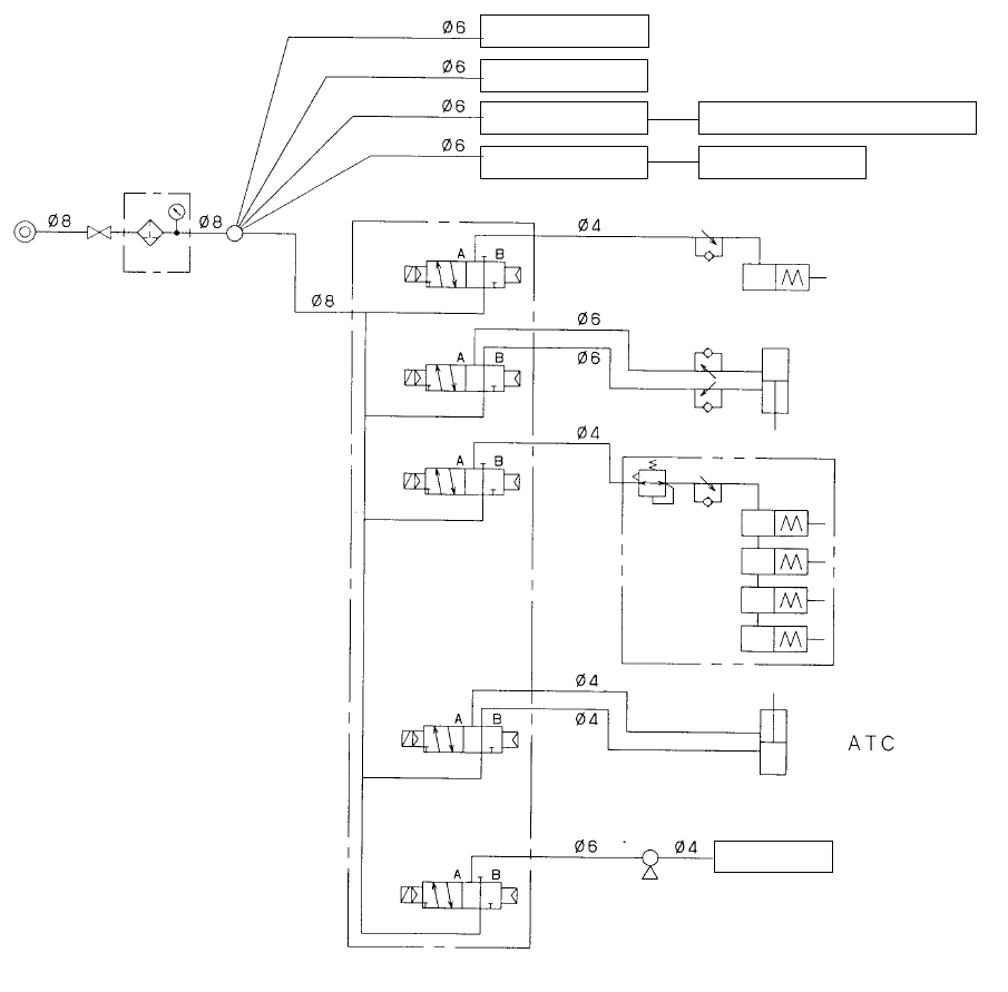
See the piping diagram shown below as the reference material.
(Filter regulator)
Drive c
y
linder F
Drive c
y
linder R
Female union 32-mm adhesive ta
p
e feeder
E
j
ector unit IC Z-slide bracket
Stopper
Support
(optional)
pusher Y (X4)
(Ejector)
CAL block
(optional)
(Electromagnetic valve)