KJ-01.02.Instruction Manual.REV.02.pdf - 第25页
1 − 9 • Least input placement ang le increment Progr ammable placement angle sett ing unit: 0.05 ° • Aut omatic tool chang er (A TC) The A T C can accommodate up t o 4 nozzles. • Transport r ail height 900 mm ± 20 mm • M…
1 − 8
1.1.4 Mechanical specifications
• Placement accuracy
The following table lists the placement accuracy data for different types of
components. A poorer accuracy results depending on the components that may
have an edge or plastic mold burrs at the area detected with the laser align
function, and that may have a moving part to be detected with respect to the pick
port.
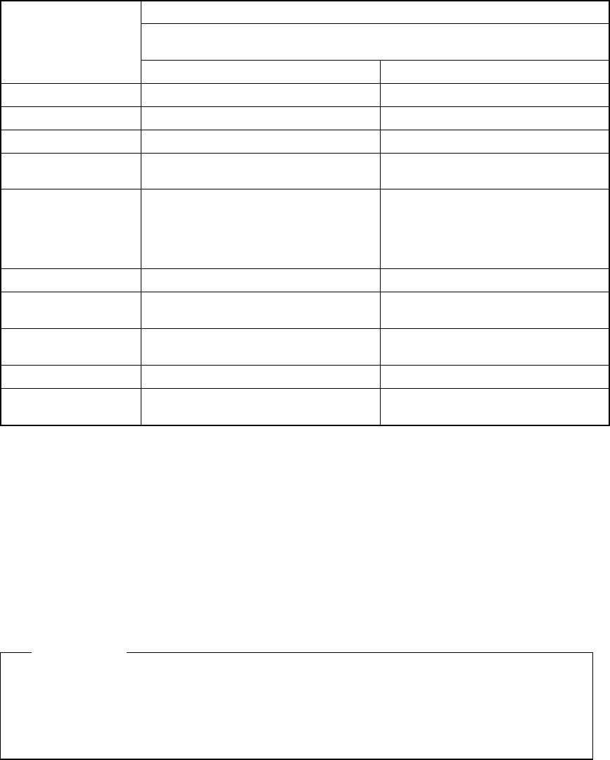
Table 1.1.4.1
KJ-01/02
LAHD heads (Laser recognition correction)
Component size: 20 mm x 20 mm or less, or 23.5 mm x 11 mm or less
Component type
Position (X, Y) Unit: (mm)
Posture (theta) Unit: (°)
Square chip
± 0.08 ± 3
MELF
± 0.1
± 3
SOT
± 0.15
± 3
Aluminum
electrolytic capacitor
± 0.3 ± 10
SOP ± 0.15 in the right angle direction
against the lead
(Burr on one side: 0.15 or less)
±0.2 in the direction parallel to the
lead
± 3
PLCC
± 0.2
± 0.3
QFP, TSOP
(Pitch: 0.8 or more)
± 0.12
± 0.3
QFP, TSOP
(Pitch: 0.65)
± 0.08
± 0.3
BGA ± 0.2
± 0.3
Other large-size
components
± 0.3
−
• Placement cycle time
The optimized placement cycle time is shown below. The cycle time required
when a component is placed on a board actually varies depending on the board
size or how many times a nozzle is replaced.
Small chip component
4,000 components/hour 0.9 seconds/component)
This cycle time is calculated with supposition that the machine picks up a
component from an 8-mm tape feeder and places it on a board at 180 degrees,
and the distance from the component pick-up point to the placement point is 80
mm or less.
[Definition]
1 − 9
• Least input placement angle increment
Programmable placement angle setting unit: 0.05°
• Automatic tool changer (ATC)
The ATC can accommodate up to 4 nozzles.
• Transport rail height
900 mm ± 20 mm
• Machine dimensions and mass
W : 698 mm
800 mm (including PWB transfer unit)
D : 735 mm
934 mm (including keyboard)
H : 1300 mm
(height of the main unit when the PWB transfer height is 900 mm)
1584 mm
(height of the vision monitor when the PWB transfer height is 900 mm)
2000 mm
(height of the signal tower when the PWB transfer height is 900 mm)
Mass: 360 kg
• Air requirements
Air pressure : 0.49 ± 0.05 Mpa
Air consumption :60 L/min.
Dry air : Atmospheric dew point -17°C or lower
• Country of manufacturing
Manufactured in Japan
• Environmental conditions
Operating
Ambient temperature: +10° C to +35° C
Relative humidity: 50% or less (at 35° C)
90% or less (at 20° C)
Transport and storage
Temperature: -25° C to +70° C
Relative humidity: 20% to 95% (No condensation)

1 − 10
1.1.5 Electrical specifications
• Control Systems
Table 1.1.5.1
Item Control system Resolution
X-Y Closed loop by AC servo motor 0.010mm
Z Semi-closed loop by AC servo motor 0.00125mm
θ (When the machine
operates normally) (KJ/01/02)
Semi-closed loop by AC servo motor
0.02°
θ (When the machine uses a
VCS to recognize a component
and places it on a board)
(KJ/01/02)
Closed loop method with the AC servo motor
and the detailed resolution encoder.
0.005°
• Main CPU
32 bitcpu
• Display
Character display : 10" color
Graphics display : 9" monochrome
• Data and program input/output
A program which has been generated with an external programming device or
manually created from the keyboard can be input by means of a 3.5" floppy disk.
(2HD/1.44 MB type only)
• Printer interface
Centronics interface
• Number of placement points
Up to 2000 placement points can be defined per program.
For multi-matrix PWBs, up to 10000 points can be defined, which is the number of
circuits multiplied by the number of placement points.
• Power requirements
Voltage : single-phase, 200 V AC (220 V, 230 V, 240V)
Apparent power : 1.1 kVA
Frequency : 50/60 Hz