KJ-01.02.Instruction Manual.REV.02.pdf - 第236页
6 − 32 2) Def ault patt ern Using the f ollowing pop-up menu, set the def ault ball pat tern incor porated into the system. T he selectable patt ern depends on a lead (ball) pit ch. See T able 6.5.2.2. T able 6.5.2.2 Req…
6 − 31
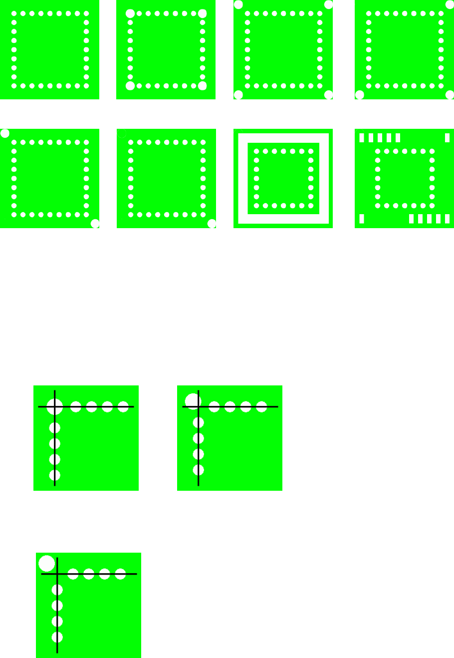
Default base style sample image
Note 1: The size of an index ball varies from a big one to a small one. In addition,
the center of the index ball is not always aligned with the center of a ball.
Then, to distinguish index marks one to four corner clearly, the index ball
position is set as follows:
When an index ball is on the ball cross pattern, it is handled as the
“Standard” type.
When an index ball is outside the ball cross pattern, it is handled as the
“Index mark one to four corner”.
Standard Index mark 4 corner Index mark 3 corner
Index mark 2 corner Index mark 1 corner Outer belt type mark Mark overspill
6 − 32
2) Default pattern
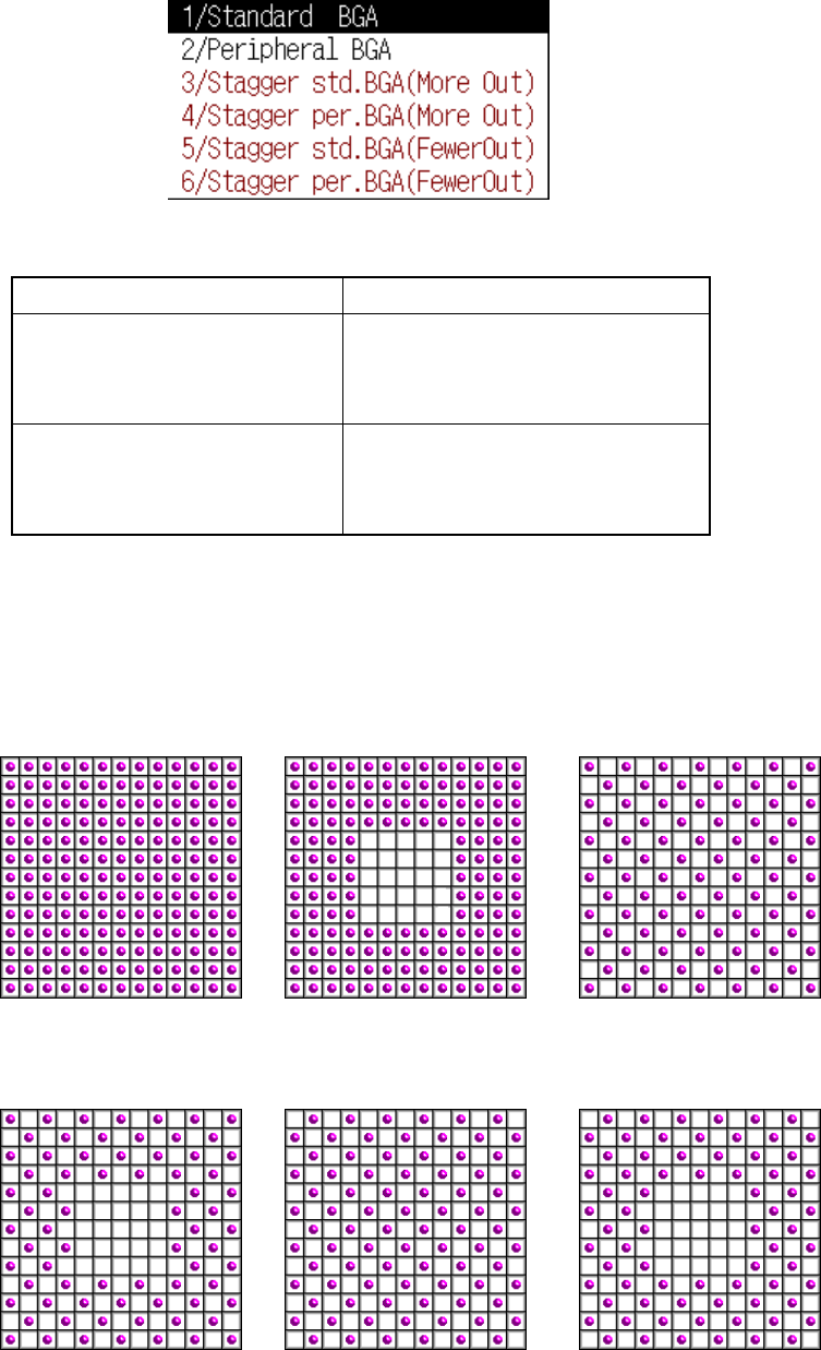
Using the following pop-up menu, set the default ball pattern incorporated into
the system. The selectable pattern depends on a lead (ball) pitch. See Table
6.5.2.2.
Table 6.5.2.2 Requirements for selecting the default pattern
Lead pitch (Ball pitch) Selectable pattern type
BGA
1.00 mm to 1.99 mm
FBGA
0.50 mm to 0.99 mm
Standard BGA
Peripheral BGA
User pattern
BGA
2.00 mm to 3.00 mm
FBGA
1.00 mm to 2.00 mm
Stagger Std. BGA (More OUT)
Stagger Std. BGA (Fewer OUT)
Stagger Per. BGA (More OUT)
Stagger Per. BGA (Fewer OUT)
If you want to use a user pattern when you select the staggered pattern, regard
the staggered pattern as the standard pattern, and suppose that a ball is located
at an area on which no ball is located. The ball pitch becomes half of the actual
one. Enter this ball pitch, which is reduced to the half, and select a user pattern.
Default pattern sample images
Standard BGA Peripheral BGA
Stagger Std. BGA
(More OUT)
Stagger Per. BGA
(More OUT)
Stagger Std. BGA
(Fewer OUT)
Stagger Per. BGA
(Fewer OUT)
6 − 33
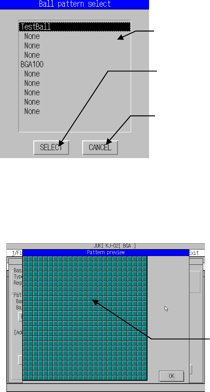
3) User pattern
Select the user ball pattern. Create a pattern with the “Ptn. edit” button in
advance according to the descriptions of Section 6.5.4 “Editing the BGA
component user ball pattern”).
4) Pattern editing
This function calls the editing function which creates a user unique ball pattern.
See Section 6.2.3 “Editing the BGA component user ball pattern” for details.
5) Preview
This function displays the set pattern.
Lists the names of the patterns which have
been created with the user pattern editing
function here.
When you move the cursor over the
pattern to be used, then press this button,
the pattern is selected.
Returns to the previous screen.
Ball pattern image
based on the set data