KJ-01.02.Instruction Manual.REV.02.pdf - 第235页
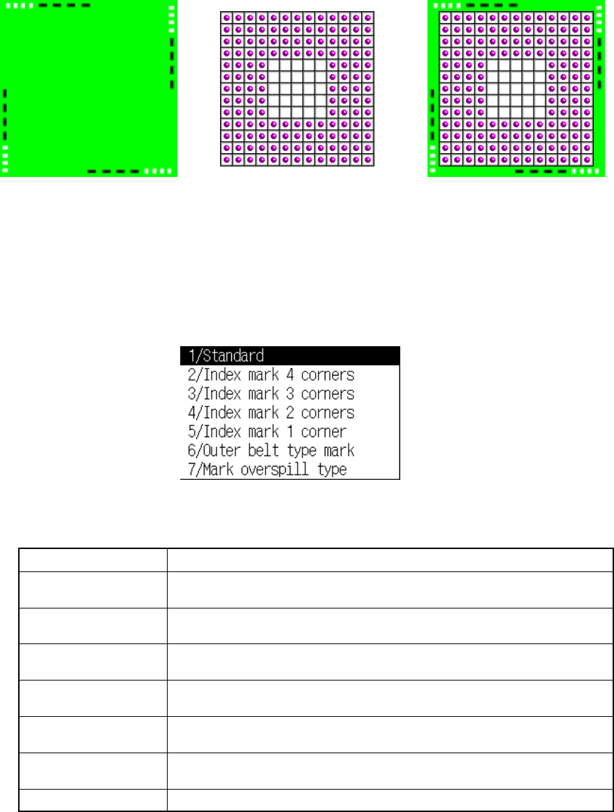
6 − 31 Default base st yle sample image Note 1: The size of an index ball varies from a big one to a small one. I n addition, the center of the index ball is not always aligned with the center of a ball. Then, to disting…
6 − 30
6.5.2 Recognition pattern
Set the BGA recognition pattern as follows:
The recognition pattern consists of the following patterns.
1) Base style
Using the following pop-up menu, specify the base style incorporated into the
system as the default.
Table 6.5.2.1 Selection conditions of patterns
Style name Descriptions
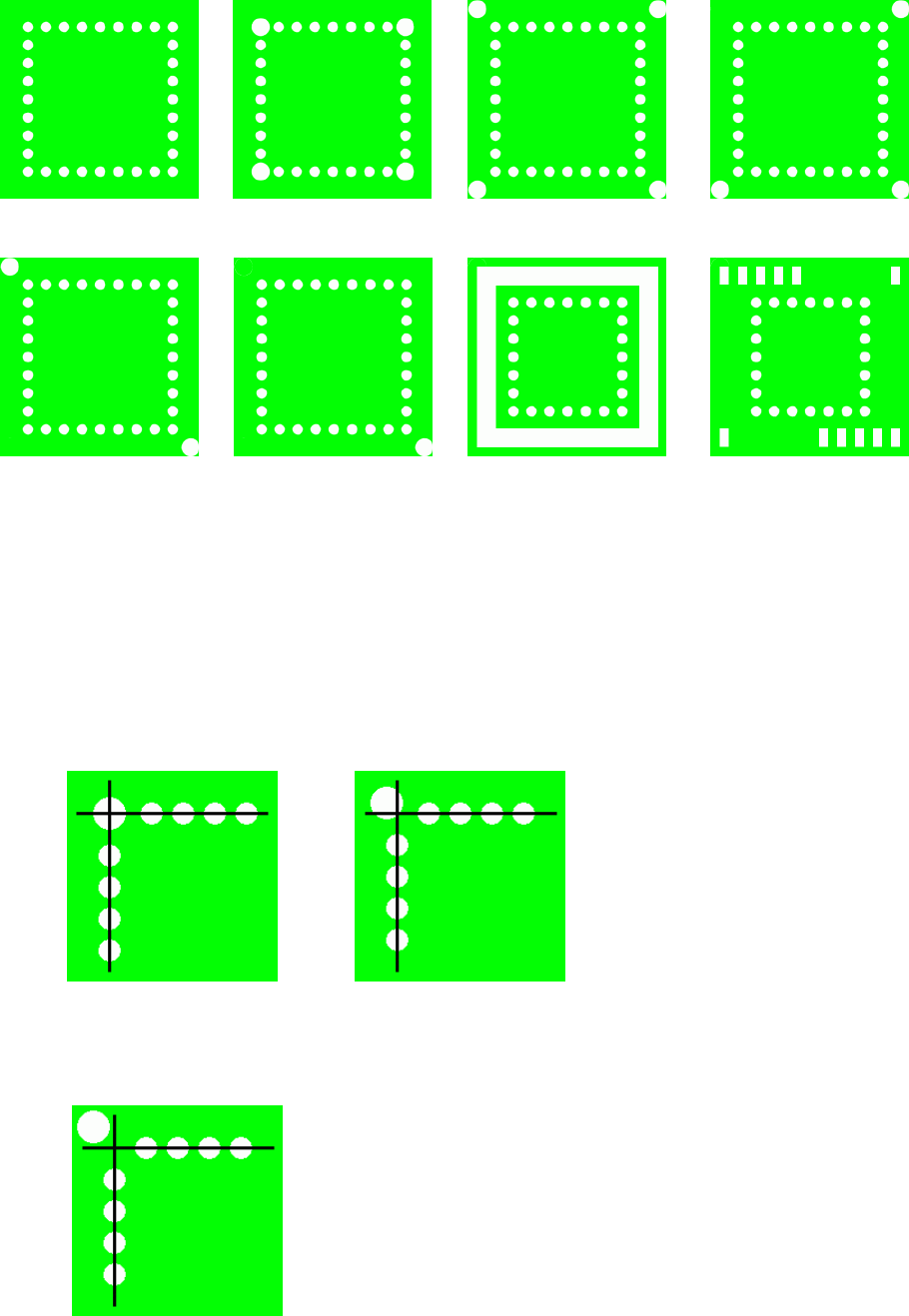
Standard There are only balls existing on the outer of the package. Index marks are
located on the cross pattern.
Index mark 4 corner There are only balls or index marks existing on the outer of the package, and
index marks are located at four corners as well as on the cross pattern.
Index mark 3 corner There are only balls or index marks existing on the outer of the package, and
index marks are located at three corners as well as on the cross pattern.
Index mark 2 corner There are only balls or index marks existing on the outer of the package, and
index marks are located at two corners as well as on the cross pattern.
Index mark 1 corner There are only balls or index marks existing on the outer of the package, and
index marks are located at one corners as well as on the cross pattern.
Outer belt type mark There are something existing in the shape of a belt whose density is like that
of balls on the outer of the package.
Mark overspil type There are something not a ball on the outer of the package.
*1 An index mark is a mark which indicates a position outside a ball, ball-shaped
partial -pressure of balls, and so on.
+
++
+
=
==
=
Base style Ball pattern
Default pattern
User pattern
Recognition pattern
6 − 31
Default base style sample image
Note 1: The size of an index ball varies from a big one to a small one. In addition,
the center of the index ball is not always aligned with the center of a ball.
Then, to distinguish index marks one to four corner clearly, the index ball
position is set as follows:
When an index ball is on the ball cross pattern, it is handled as the
“Standard” type.
When an index ball is outside the ball cross pattern, it is handled as the
“Index mark one to four corner”.
Standard Index mark 4 corner Index mark 3 corner
Index mark 2 corner Index mark 1 corner Outer belt type mark Mark overspill
6 − 32
2) Default pattern
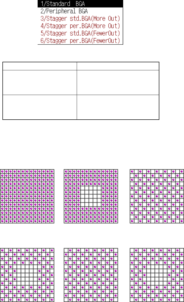
Using the following pop-up menu, set the default ball pattern incorporated into
the system. The selectable pattern depends on a lead (ball) pitch. See Table
6.5.2.2.
Table 6.5.2.2 Requirements for selecting the default pattern
Lead pitch (Ball pitch) Selectable pattern type
BGA
1.00 mm to 1.99 mm
FBGA
0.50 mm to 0.99 mm
Standard BGA
Peripheral BGA
User pattern
BGA
2.00 mm to 3.00 mm
FBGA
1.00 mm to 2.00 mm
Stagger Std. BGA (More OUT)
Stagger Std. BGA (Fewer OUT)
Stagger Per. BGA (More OUT)
Stagger Per. BGA (Fewer OUT)
If you want to use a user pattern when you select the staggered pattern, regard
the staggered pattern as the standard pattern, and suppose that a ball is located
at an area on which no ball is located. The ball pitch becomes half of the actual
one. Enter this ball pitch, which is reduced to the half, and select a user pattern.
Default pattern sample images
Standard BGA Peripheral BGA
Stagger Std. BGA
(More OUT)
Stagger Per. BGA
(More OUT)
Stagger Std. BGA
(Fewer OUT)
Stagger Per. BGA
(Fewer OUT)