KJ-01.02.Instruction Manual.REV.02.pdf - 第85页
4 − 14 (3) Production oper ation T able 4.3.3.1 Placement when set for “Unused” No. Unit Production operation 1 OCC The machine places a component on a board w ithout recognizing any BOC mark. 2 Bad mark sensor The machi…
4 − 13
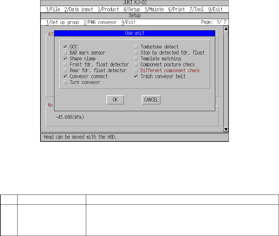
4.3.3 Use Unit
When you select the [3/Use Unit] command from the [1/Set up group] menu, the “Use
Unit” dialog box appears on the screen as shown in Figure 4.3.3.1.
Figure 4.3.3.1 Use Unit setting dialog box
(1) Setting items
No. Item Description
1 Use Unit
Unit to be used/not used
Should a system unit develop a malfunction, that unit may be defined as "a
unit not used" using this command. This allows the pick-and-place sequence
to be executed without modifying the production program data.
Table 4.3.3.1 shows whether or not a pick-and-place sequence can be completed
if the production program requires the unit defined as to be used before it can
complete itself.
(2) Setting the unit
– Specify the device unit to be used with the check box.
– Any unit without option setting being made cannot be checked.
4 − 14
(3) Production operation
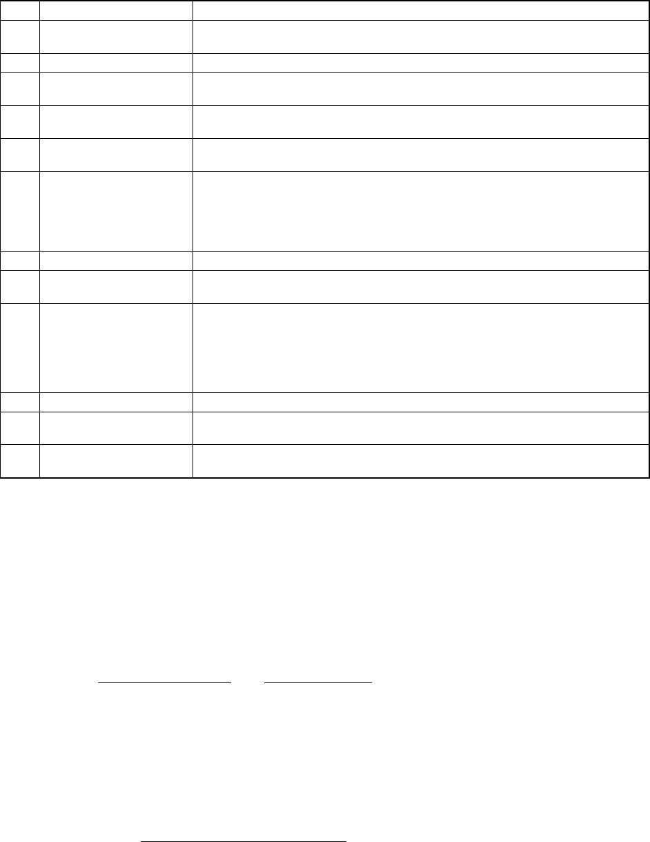
Table 4.3.3.1 Placement when set for “Unused”
No. Unit Production operation
1 OCC The machine places a component on a board without recognizing any BOC
mark.
2 Bad mark sensor The machine places a component on a board without detecting any bad mark.
3 Shape clamp The machine places a component on a board without using a shape reference
unit.
4 Front feeder float detector The machine deletes only the function of the front feeder float detector, and then
places a component on a board.
5 Rear feeder float detector The machine deletes only the function of the rear feeder float detector, and then
places a component on a board.
6 Conveyor connect The machine places a component on a board normally.
Note: If you want to start production while a board is located over the IN
sensor, be sure to set the board so that its 30-mm or wider section can
be located over the IN sensor. If you fail to set a board in this way, the
machine may not fix the board.
7 Turn conveyor Places components on a board normally.
8 Tombstone detect Placement is carried out without chip rise detection even when chip rise
detection for Component data is designated.
9 Stops immediately at the
feeder float detected
The XY speed becomes slower when the sensor detects feeder floating while the
XY axe are moving.
When the sensor detects feeder floating before the XY axes moves, the machine
asks the operator whether to retry the sensor detection operation.
When the operator selects “Retry”, the sensor reconfirms feeder floating.
When he or she selects “Cancel”, the production is terminated.
10 Template matching Not performed
11 Component posture
check
Not performed (Note2)
12 Different component
check
Not performed
Note: The following items are checked as the odd shape component detection function.
– Horizontal/vertical ratio checking
The laser measurement operation is controlled to detect the shorter side at first
based on the dimensions of the component data. The first minimum width is
compared with the second minimum width which are the result of the measurement
operation for the shorter side and the longer side of the component data. If the
difference between them is not within the certain range, the component posture error
is supposed to occur.
Shorter side of the
component data
First minimum
width
Longer side of the
component data
Second
minimum width
> Reference →
value
Component
posture error
The “Different component check” is performed as follows:
If the result value is to be on the shorter side, the limits can be calculated based on
the reference value of the shorter side. If it is on the longer side, the limits can be
calculated based on the reference value of the longer side.
Result value - Reference value
Lower
limit
<
Reference value
X 100 > Upper limit →
The component passed the
different component check.
4 − 15
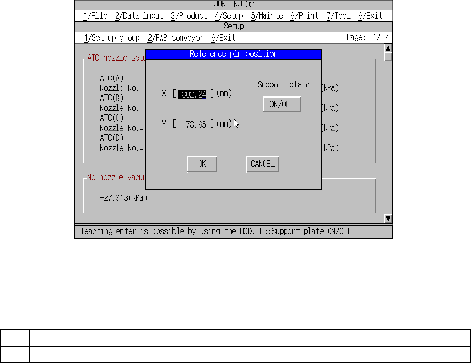
4.3.4 Reference pin position
When you select the [4/ Reference pin position] command from the [1/Set up group]
menu, the “Reference pin position” dialog box appears on the screen as shown in
Figure 4.3.4.1.
Figure 4.3.4.1 Reference pin position setting dialog box
(1) Setting items
No. Item Description
1 Reference pin (X, Y) Reference pin position
(2) How to set
– Key in X and Y coordinate values directly from the keyboard.
– Use HOD to teach and enter the coordinates. In this case, both the X and Y
values are entered with either X or Y be in focus.