KJ-01.02.Instruction Manual.REV.02.pdf - 第170页
5 − 74 5.5.2 Commands The local commands t hat can be called f rom t he Component dat a are shown below . <1> File menu T he operation is t he same as that for the PW B data. <2> Edit menu T able 5.5.2. 1 lis…
5 − 73
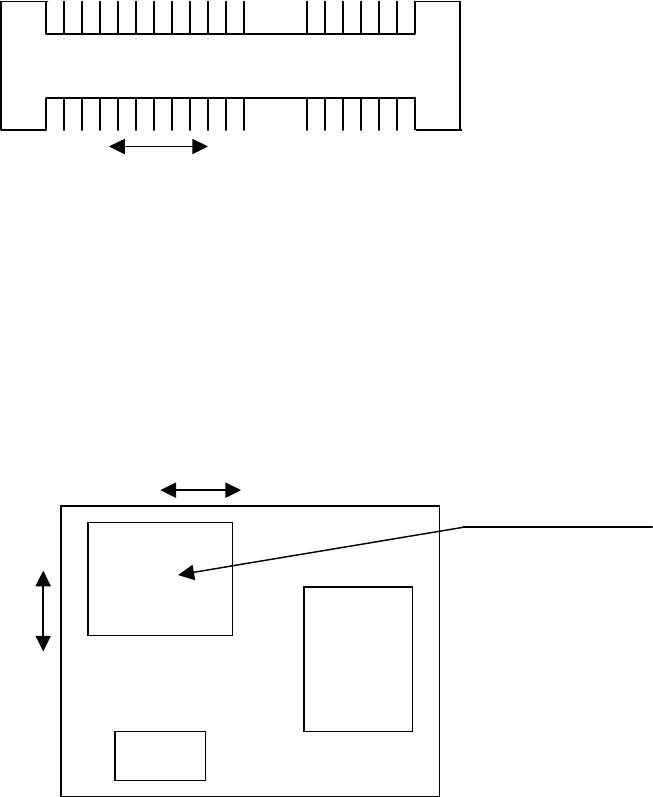
⑬ Recong. offset X, Y
Enter the offset from the nozzle component pick-up point to the recognition
center point.
- Example of a connector
+ indicates the nozzle component pick-up point.
*
indicates the recognition center point.
Recognition center of a connector
In this case, X = - 7.06, and Y = 0.00.
- If the area to be picked up is limited
Recognition center offset generated if the area the machine can pick up is limited
In the case above, X =3.20 and Y = 4.00.
The range of coordinates you can enter is not affected with the component
supply angle. Enter coordinates viewed from the direction of a component
when supplied.
⑫ Dimension check
(* The current version of the machine cannot handle this function.)
See the description of the corresponding item provided when a component is
centered with laser.
+ *
7.06
*
+
+ indicates the nozzle pick-up point.
* indicates the recognition center point.
3.2
4.0
Area the machine can pick up
5 − 74
5.5.2 Commands
The local commands that can be called from the Component data are shown below.
<1> File menu
The operation is the same as that for the PWB data.
<2> Edit menu
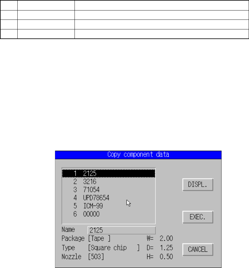
Table 5.5.2.1 lists the selectable commands and the characters displayed on the
message line.
Table 5.5.2.1 Messages displayed on the message line when you select the edit command
No. Command Characters displayed on the message line
1 Copy Copy block unit.
2 Delete Delete block unit.
3 Component name Change component name with dialog.
(1) Copy
This command can be executed on the Component data form screen only.
① Operation
This command copies data excluding a component name and comment
you selected on the “Copy component data” dialog box to data of a
component displayed on the Component data form screen.
Select a component you wan to copy from the list box, and click the
<EXEC> button. The machine copies the selected data.
Move the cursor to the component name column, select the desired
component name, and click the <DISPL.> button to select a component.
Figure 5.5.2.1 Copy component data dialog box
5 − 75
(2) Delete
① Operation
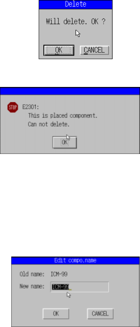
If the component at the cursor line is not listed in the placement data,
delete that data.
After the data has been deleted, either of the following dialog boxes
appears depending on the situation.
Figure 5.5.2.2 Dialog box confirming deletion
Figure 5.5.2.3 Dialog box informing deletion is not possible
The cursor stays at the same position after “delete” has been executed. The
data below the deleted line moves up by one line.
(3) Component name
① Operation
This operation changes the component name registered in the
Component data currently displayed on the Component data screen.
Figure 5.5.2.4 Edit compo. name dialog box