KJ-01.02.Instruction Manual.REV.02.pdf - 第258页
7 − 8 7.3 Teaching Recogniti on 7.3.1 Teaching of a Board Mark The f ollowing describes the basic operat ing procedur e for teaching r ecognit ion. 1. Move the cursor to the m ark of the desir ed data position. T o star …

7 − 7
7.2.3 Teaching Z-axis
For Z-axis teaching, the operator must first select the device with which Z-axis is to
be taught as described in the procedure given in 7.2.1 “Basic operating procedure”.
Only the head can be selected as the device. An error results with an alarm beep if
any other device is selected, and the operator must starts the operation from the
device selection.
This teaching is for height teaching. Lift down slowly the nozzle tip until it touches the
object for measurement, and measure the height. Never push the nozzle into the
object. After selection is made, the same method applies.
CAUTION
When you use the ↓-Z key to perform Z-axis teaching, the Z-axis
immediately moves down to the point 6 mm lower than the height you
set.
This may damage a nozzle, so do not perform Z-axis teaching around
the PWB transport rails (reference pin position or follower pin position)
or directly above a tall component.
7.2.4 Teaching vacuum value
Vacuum values are automatically set when component measurement is performed.
So, teaching is not necessary.
7 − 8
7.3 Teaching Recognition
7.3.1 Teaching of a Board Mark
The following describes the basic operating procedure for teaching recognition.
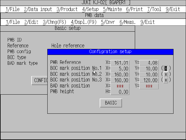
1. Move the cursor to the mark of the desired data position.
T o start teaching recognition, X- and Y-coordinates of the mark shall be entered
beforehand.
Figure 7.3.1.1
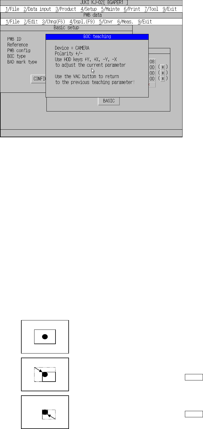
2. Press the CAMERA key on the HOD to start teaching.
The camera moves to the X- and Y-coordinates of the mark, and the selected
mark appears on the monitor. If the mark does not appear on the monitor, check
if the entered coordinates are correct.
If you do not use a camera as a teaching device, an error sound beeps, and the
machine cannot perform teaching recognition.
7 − 9
Figure 7.3.1.2
3. Use the +Y and/or –Y key of the HOD to select which direction the recognized
image data is to be rotated: positive or negative. After selecting the rotating
direction, press the ENTER key.
Note: The machine detects a white part as a mark. Whether the mark is
recognized as white or black with respect to the board color depends on
the contrast between the mark and the board, and on the light level for
the camera’s field of view. Normally, the mark is recognized as white. If,
however, there are lands, patterns, or silk printings around the field of
view of camera, the mark may be recognized as black with respect to the
board color. In this case, normal correction is impossible. Reverse the
black and white by pressing the +Y or -Y key on the HOD so that the
mark appears as white. If a mark is recognized as black against the
board, press the +Y or -Y key to reverse the black and white so that the
mark can be recognized as white.
4. Adjust the scale frame.
Set the top, left, bottom and right sides of the scale frame with the direction key
(+Y, -Y, +X and/or –X) to adjust the size of the scale frame
The FAST key changes the moving distance of the scale frame.
The camera picture and a rectangle frame appear.
Set the top and left scale frames first. Adjust them
so that they match with the top and left of the mark.
When adjustment is complete, press the ENTER
key.
In the same manner as above, set the bottom and
right scale frames.
When adjustment is complete, press the ENTER
key.