KJ-01.02.Instruction Manual.REV.02.pdf - 第339页
10 − 14 10.4.4 Laser control W hen y ou select the [ 4/Laser] com mand on the menu bar , and then t he [1/Laser control] com mand on the displayed menu, t he dialog box f or controlling laser appears on the screen as sho…
10 − 13
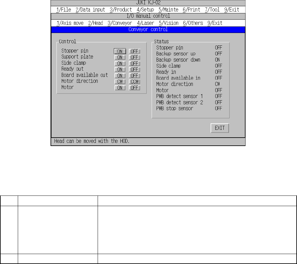
10.4.3 Conveyor control
When you select the [3/Conveyor] command on the menu bar, and then the
[1/Conveyor control] command on the displayed menu, the dialog box for controlling
the PWB transport system appears on the screen as shown in Figure 10.4.3.1.
Each command is described on Table 10.4.3.1.
Figure 10.4.3.1 “Conveyor control” dialog box
Table 10.4.3.1 Description of each command
No. Command Setting/displayed items
1 Control Stopper pin (ON/OFF)
Support plate (ON/OFF)
Side clamp (ON/OFF)
Ready out (ON/OFF)
Board available out (ON/OFF)
Motor direction (CW/CCW)
Motor (ON/OFF)
2 Status Displays each operation control condition and the sensor condition.
When you click a button displayed on the dialog box above, and press the ENTER
key of a keyboard or click the trackball, the system starts controlling the
corresponding operation.
The controlled condition is displayed in real time.
10 − 14
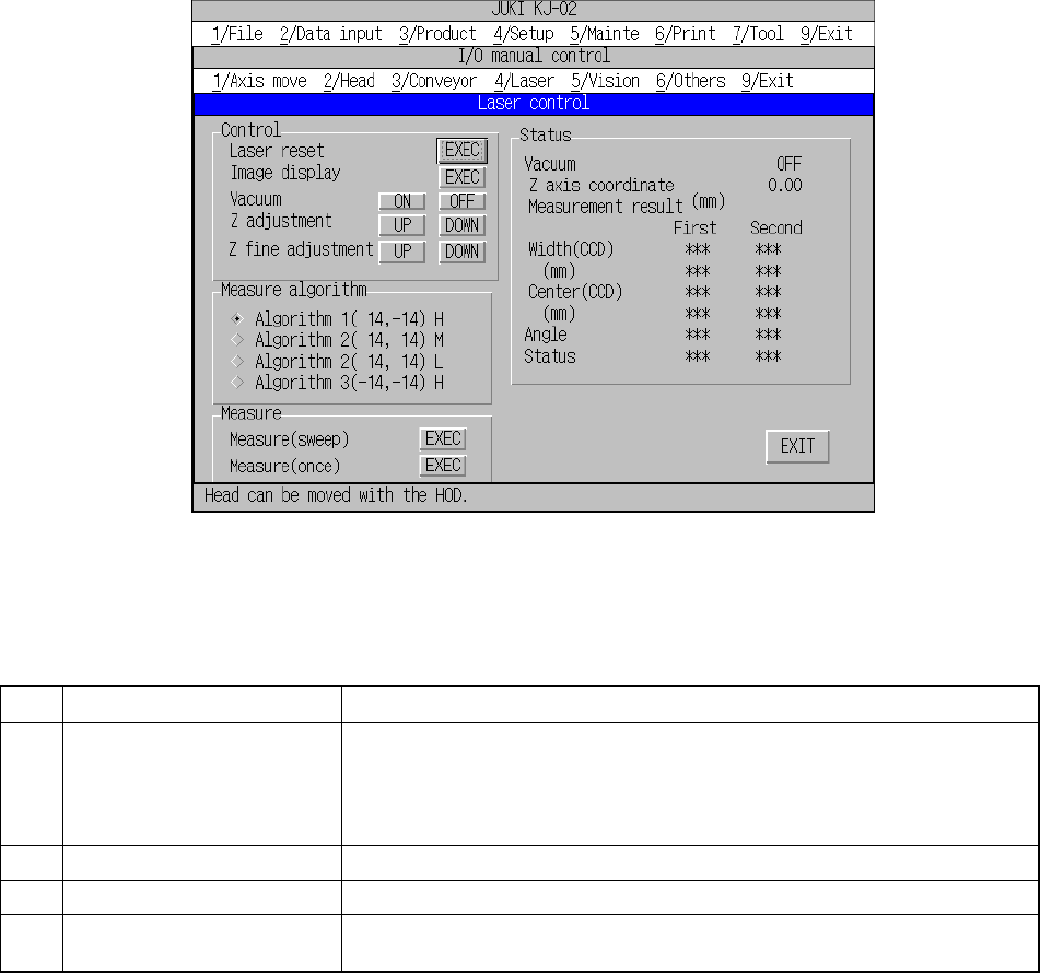
10.4.4 Laser control
When you select the [4/Laser] command on the menu bar, and then the [1/Laser
control] command on the displayed menu, the dialog box for controlling laser appears
on the screen as shown in Figure 10.4.4.1.
Each command is described on Table 10.4.4.1.
Figure 10.4.4.1 “Laser control” dialog box
Table 10.4.4.1 Description of each command
No. Command Setting/displayed items
1 Control Laser reset (initialization of laser), Image display, Vacuum (ON/OFF)
(nozzle vacuum condition), Z adjustment (Z-axis adjustment of the nozzle)
(UP: height of the side to be detected with laser)/DOWN: XY-direction
movable lowest limit), and Z fine adjustment (Z-axis fine adjustment of the
nozzle) (UP: 0.01 mm/DOWN: 0.01 mm)
2 Measure algorithm Selects the algorithm for measuring a component with laser.
3 Measure Measures by rotating or measures without rotating.
4 Status Displays each operation control condition, or measurement result with
laser.
When you select a button displayed on the dialog box above, the corresponding
control operation starts. The controlled condition is displayed in real time.
10 − 15
10.4.5 Vision
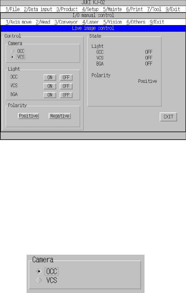
10.4.5.1 Live image control
When you select the [1/Live image control] command on the “5/Vision” menu, the
“Live image control” dialog box appears as shown in Figure 10.4.5.1.1.
Figure 10.4.5.1.1 Live image control screen (Screen example when you use a KJ-02)
− Camera
Select a camera whose image is to be displayed by clicking the corresponding
radio button.
Note that you cannot select a unit whose view type is not set (that is, not
installed) with the "Option" menu of the MS parameters.
This selection will not affect the setting of the "Device enable" dialog box invoked
from the Machine setup menu (you can select a unit not).
(You can select a unit that is not to be used on the “Use unit” menu.)
Live image control camera selection dialog box
− Polarity
By clicking the corresponding radio button, you can switch the polarity of image
displayed on the monitor: positive or negative
The state of the back light is updated when the back light is controlled completely.