KJ-01.02.Instruction Manual.REV.02.pdf - 第169页
5 − 73 ⑬ Recong . off set X , Y Enter the off set f rom t he nozzle component pick-up point t o the recog nition center point. - Example of a connector + indicates the nozzle component pick-up point. * indicates the reco…
5 − 72
(2) When centering a component with the VCS (not available to a KJ-01)
① Retry times
Set this item in the same manner as when you center a component with laser.
② Placing stroke
Set this item in the same manner as when you center a component with laser.
③ Picking stroke
Set this item in the same manner as when you center a component with laser.
④ Trial
Set this item in the same manner as when you center a component with laser.
⑤ Picking Z down
Set this item in the same manner as when you center a component with laser.
⑥ Picking Z up
Set this item in the same manner as when you center a component with laser.
⑦ Placing Z down
Set this item in the same manner as when you center a component with laser.
⑧ Placing Z up
Set this item in the same manner as when you center a component with laser.
⑨ Theta speedSet this item in the same manner as when you center a component
with laser.
⑩ Compo. aband.
Set this item in the same manner as when you center a component with laser.
⑪ Placing offset X, Y
Set this item in the same manner as when you center a component with laser.
⑫ Picking depth
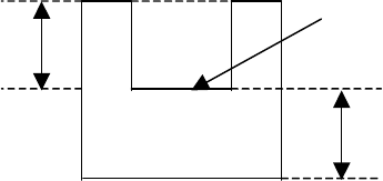
If the top side of a component (component height: t) is located at a higher
level than the side the machine is to pick because its shape is concave and its
sides protrude, enter the offset value (X) from the side the machine picks using
the formula bar. The allowable input value range is from 0 mm to 14 mm.
Explanation of “Picking depth”
x
t
Side to be picked up
x: pick depth
t: component height
5 − 73
⑬ Recong. offset X, Y
Enter the offset from the nozzle component pick-up point to the recognition
center point.
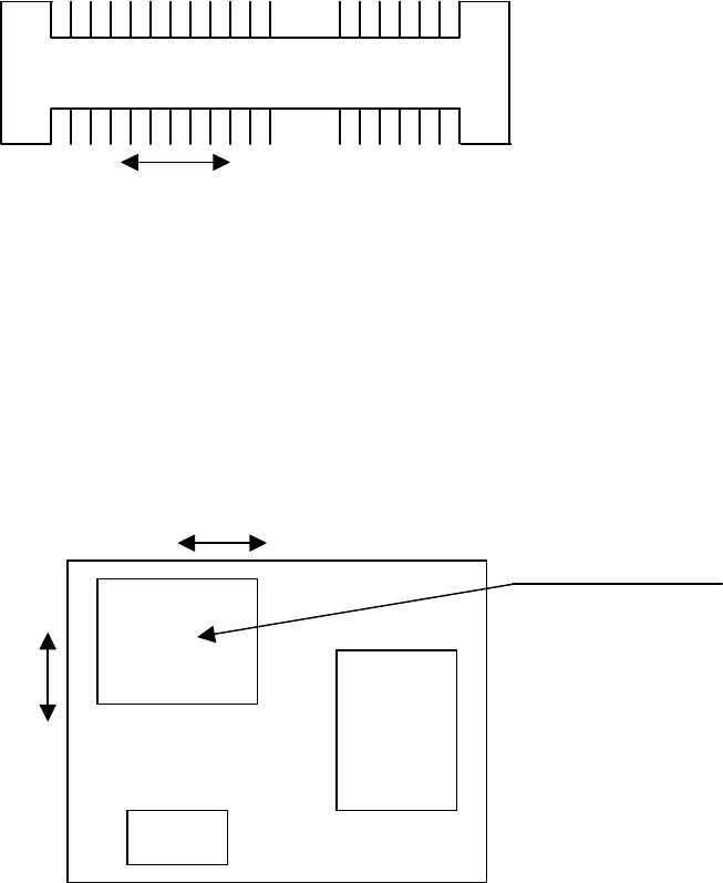
- Example of a connector
+ indicates the nozzle component pick-up point.
*
indicates the recognition center point.
Recognition center of a connector
In this case, X = - 7.06, and Y = 0.00.
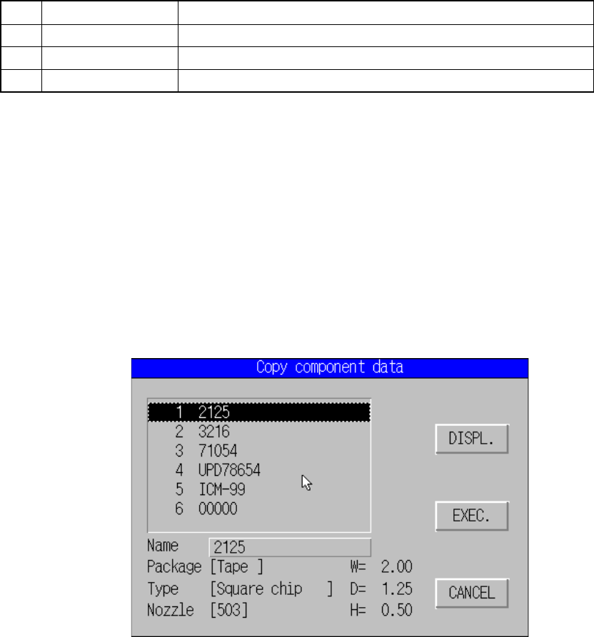
- If the area to be picked up is limited
Recognition center offset generated if the area the machine can pick up is limited
In the case above, X =3.20 and Y = 4.00.
The range of coordinates you can enter is not affected with the component
supply angle. Enter coordinates viewed from the direction of a component
when supplied.
⑫ Dimension check
(* The current version of the machine cannot handle this function.)
See the description of the corresponding item provided when a component is
centered with laser.
+ *
7.06
*
+
+ indicates the nozzle pick-up point.
* indicates the recognition center point.
3.2
4.0
Area the machine can pick up
5 − 74
5.5.2 Commands
The local commands that can be called from the Component data are shown below.
<1> File menu
The operation is the same as that for the PWB data.
<2> Edit menu
Table 5.5.2.1 lists the selectable commands and the characters displayed on the
message line.
Table 5.5.2.1 Messages displayed on the message line when you select the edit command
No. Command Characters displayed on the message line
1 Copy Copy block unit.
2 Delete Delete block unit.
3 Component name Change component name with dialog.
(1) Copy
This command can be executed on the Component data form screen only.
① Operation
This command copies data excluding a component name and comment
you selected on the “Copy component data” dialog box to data of a
component displayed on the Component data form screen.
Select a component you wan to copy from the list box, and click the
<EXEC> button. The machine copies the selected data.
Move the cursor to the component name column, select the desired
component name, and click the <DISPL.> button to select a component.
Figure 5.5.2.1 Copy component data dialog box