KJ-01.02.Instruction Manual.REV.02.pdf - 第44页
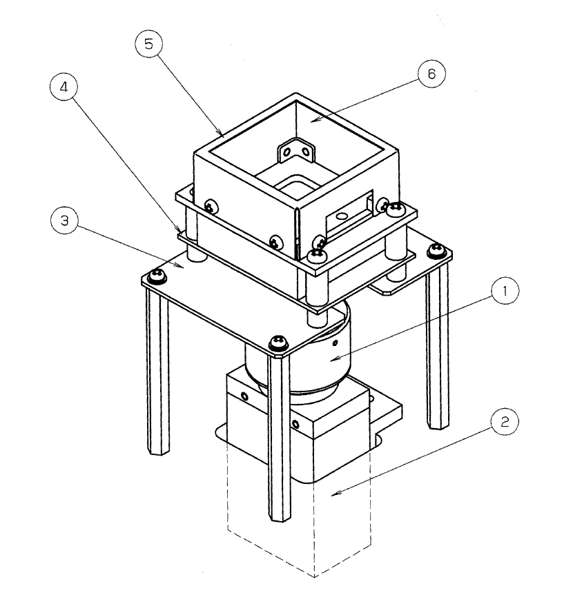
1 − 28 1.2.8 VCS: parts identification ( only for a KJ-02) ① VCS lens ② VCS camera ③ Light base ④ Illum ination LED board ⑤ CSP diff user cover ⑥ BGA lig ht LED boar d Figure 1.2.8
1 − 27
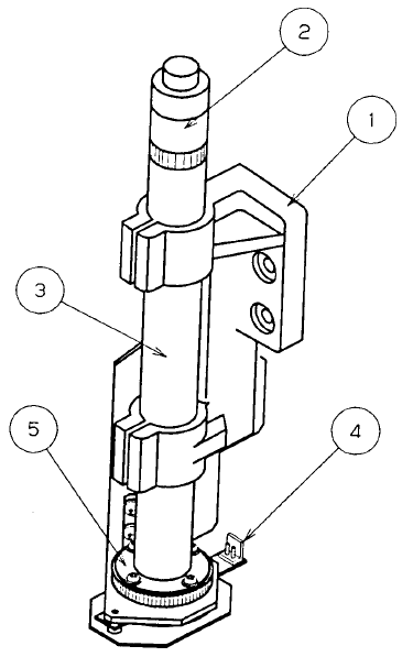
1.2.7 OCC parts identification
(1) Offset correction camera
The machine is equipped with a coaxial light and polarizing filter as the standard
devices. The camera detects a BOC mark and corrects the detected mark
automatically.
① Camera holder
② CCD camera
③ CCD camera lens
④ Illumination LED board
⑤ Polarizing filter
Figure 1.2.7.1
1 − 28
1.2.8 VCS: parts identification (only for a KJ-02)
① VCS lens
② VCS camera
③ Light base
④ Illumination LED board
⑤ CSP diffuser cover
⑥ BGA light LED board
Figure 1.2.8
1 − 29
1.3 X, Y, and Z Axes Descriptions
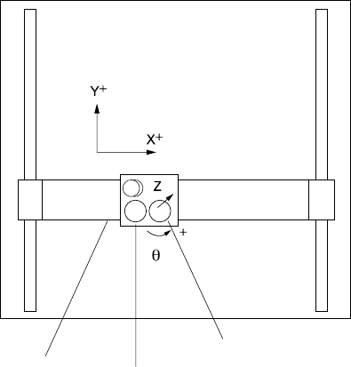
The following four axes (X, Y, Z, and θ) are numerically controlled in this machine.
(1) X- and Y-axis
The X-axis and Y-axis represent the position of the head, OCC, HMS (Height
measurement system), and bad mark sensor. The coordinates of a position are
given as X = ○○○.○○ mm and Y = ○○○.○○ mm, in 0.01-mm increments.
Two coordinate systems are available: software coordinates and tooling-pin (hole
reference) coordinates. Software coordinates mainly show the pickup position
taught in the teach mode, while tooling-pin coordinates represent the placement
position.
(2) Z-axis
The Z-axis represents the position of the nozzle in the head, given as Z = ○○.○○
mm, in 0.01-mm increments. The upward direction is positive (+), with the position
of the nozzle tip on the board being 0.
(3) θ-axis
The θ -axis represents the angle for centering of the head “A = ○○.○○ .” (in 0.05
increments.) The value is positive for counterclockwise rotation and negative for
clockwise rotation.
Figure 1.3.1
X axis
Y axis
Head unit
Bad mark sensor
OCC