KJ-01.02.Instruction Manual.REV.02.pdf - 第230页
6 − 26 ⑥ Components whose side roughness for ming a linear por tion is 0.1 mm or less Fig. 6.4. 2.7 Explanatory Draw ing of Recogniti on Condition ⑥ ⑦ Components whose component shape is not convex. W hen the abov e cond…
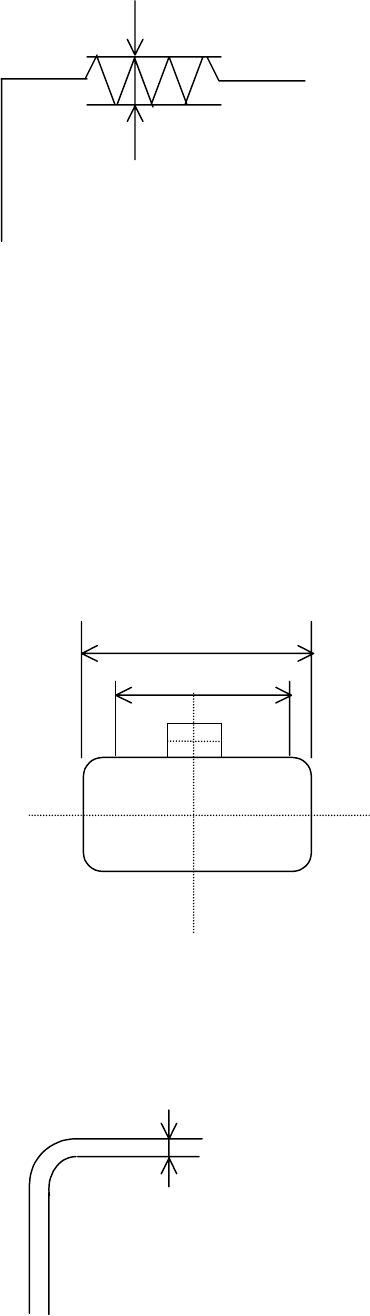
6 − 25
⑧ Components whose side roughness forming a linear portion is 0.1 mm or
less
Fig. 6.4.2.4 Explanatory Drawing of Recognition Condition ⑧
When the above recognition conditions are satisfied, corner recognition is enabled.
(2) Side recognition
① Components whose whole shape is a rectangle or regular square
② Components whose linear portion (line segment) of a side is 1/2 or more of
the component outline size but whose linear portion (line segment) should be
3 mm or more
③ Components whose sides are 0.3 mm or more when their insides are
imaged darkly at imaging
Fig. 6.4.2.5 Explanatory Drawing of Recognition Conditions ①
①①
①, ②
②②
② and ③
③③
③
④ Components whose component angle is within 90± 0.5.
⑤ Components whose sides are 0.3 mm or more when their insides are
imaged darkly at imaging
Fig. 6.4.2.6 Explanatory Drawing of Recognition Condition ⑤
⑤⑤
⑤
0.1 mm or less
Component outline size
Line segment
1.5mm
1.5mm
0.3 mm or more
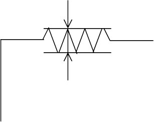
6 − 26
⑥ Components whose side roughness forming a linear portion is 0.1 mm or
less
Fig. 6.4.2.7 Explanatory Drawing of Recognition Condition ⑥
⑦ Components whose component shape is not convex.
When the above conditions are satisfied, side recognition is enabled.
(3) Center recognition
Recognition conditions
① Components whose ratio of width to length is 1:2 or more
② Components whose side portion is 0.3 mm or more (The inside of a side
may be hollow at imaging.)
When the above conditions are satisfied, center recognition is enabled.
Note: Concavity and convexity may exit on the component outline. However,
they have an effect on the center position and inclination.
In this case, adjust the placement data, etc.
0.1 mm or less
6 − 27
6.4.3 Recognition component examples
The components to be supported by the component outline recognition function are
those whose shapes are close to a rectangle or regular square.
The edges forming an outline should be 0.3 mm or more.
Black components cannot be recognized.
The machine can recognize the center of a component if the length of its longer side
is twice or more the length of its shorter side.
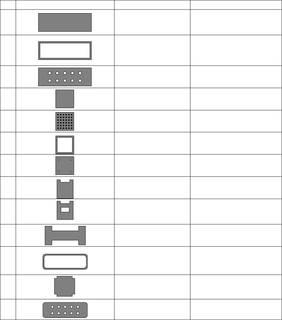
In the component drawing shown in the following table, the black/white is reversed
unlike the reality.
Table 6.4.3.1 Recognition Components Table
No. Recognition component shape Recognition method Remarks
1 Center recognition (Note)
Side recognition
Corner recognition
Rectangular component
2 Center recognition (Note)
Side recognition
Corner recognition
The inside of the component is
hollow.
Outline edge should be 0.3 mm or
more.
3 Center recognition (Note)
Side recognition
Corner recognition
The inside of the component is
undefined.
4
Side recognition
Corner recognition
Square component
5 Side recognition
Corner recognition
CBGA
6 Side recognition
Corner recognition
The inside of the component is
hollow.
7 Side recognition
Corner recognition
The inside of the component is
hollow.
8 Corner recognition The side shape is concave.
9
Corner recognition The side shape is concave.
The inside of the component is
undefined.
10 Corner recognition
Center recognition (Note)
The side shape is concave.
However, only components of
point symmetry.
11 Side recognition
Center recognition (Note)
The inside of the component is
hollow.
The outline edge should be 0.3
mm or more.
12
Side recognition
Missing corner
13 Side recognition
Center recognition (Note)
Missing corner. The inside shape
is undefined.
Note: Center recognition is enabled when the longer side is twice or more as long as the
shorter side.