Hanwha SM481 PLUS Series Administrator’s Guide Eng.pdf.pdf - 第103页
4-21 Tools Shortcut M enu <Find Surface T ouch Z Height> button It is used to chec k the Z axis height at the point in the work area accordi n g to the selected device. It is enabled when selecting ‘Z’ in the <…

4-20
Fast Flexible Placer SM481(L) PLUS Administrator’s Guide
R: Select R-axis driving motor of the head
Mirror: Select the driving motor of mirror for the fly camera.
Conv. Width: Select the motor for adjustment of conveyor width.
<Head Device> combo box
Select the object becoming the reference of the coordinates for the corresponding
position when moving to the position setup in the <Position> area using the driving
motor selected in the <Axis> combo box. Selectable objects are as follows;
Fid Cam1: Set the coordinate based on the position of the front fiducial camera.
Head1~Head6: Set the position coordinates based on the positions of the #1 ~ #6
heads.
The SM421F Model set the position coordinates based on the positions of the #1 ~
#4 heads.
<Speed Level> group
Select the speed level while operating the selected driving motor.
Selectable speed levels are as follows;
1: Operate the selected motor at the fastest speed.
2: Operate the selected motor at the fast speed.
3: Operate the selected motor at the middle speed.
4: Operate the selected motor at the slow speed.
5: Operate the selected motor at the slowest speed.
<Position> group
Used for inputting the coordinates of the position to move, moving the object as a
reference to the selected device for the position of inputted coordinates, and obtaining
the present coordinates of the object. The values input in the edit box are as follows.
X: Coordinates of X-axis
Y: Coordinates of Y-axis
If the selected object is the motor for adjustment of conveyor width, the input
value is not the Y coordinate but rather the conveyor width.
Z: Coordinates of Z-axis
R: Angle of Theta-axis
<Move> button
Used for moving the object to the position of input coordinates with reference to
the selected device.
<Get> button
Obtain the present position (coordinates or angle) of the selected object and
indicate the result in the status indication area.
4-21
Tools Shortcut Menu
<Find Surface Touch Z Height> button
It is used to check the Z axis height at the point in the work area according to the
selected device. It is enabled when selecting ‘Z’ in the <Axis> combo box.
<Origin> combo box
Select the method of choosing the reference origin. Selectable reference origin is as
follows.
Machine Logical: Assign the origin of equipment as a reference origin.
FeederBase Front (1): Assign the origin of the front feeder row as a reference origin.
FeederBase Rear (2): Assign the origin of the rear feeder row as a reference origin.
Status Indication Area
Indicates the information generated during manual operation.
<Park Front> button
Move the front gantry near to the front ANC, and the rear gantry near to the Y2 +
Limit position.
<Park Rear> button
Move the front gantry near to the Y1 + Limit position, and the rear gantry near to the
rear ANC.
4.7.2. Head Tab dialog box
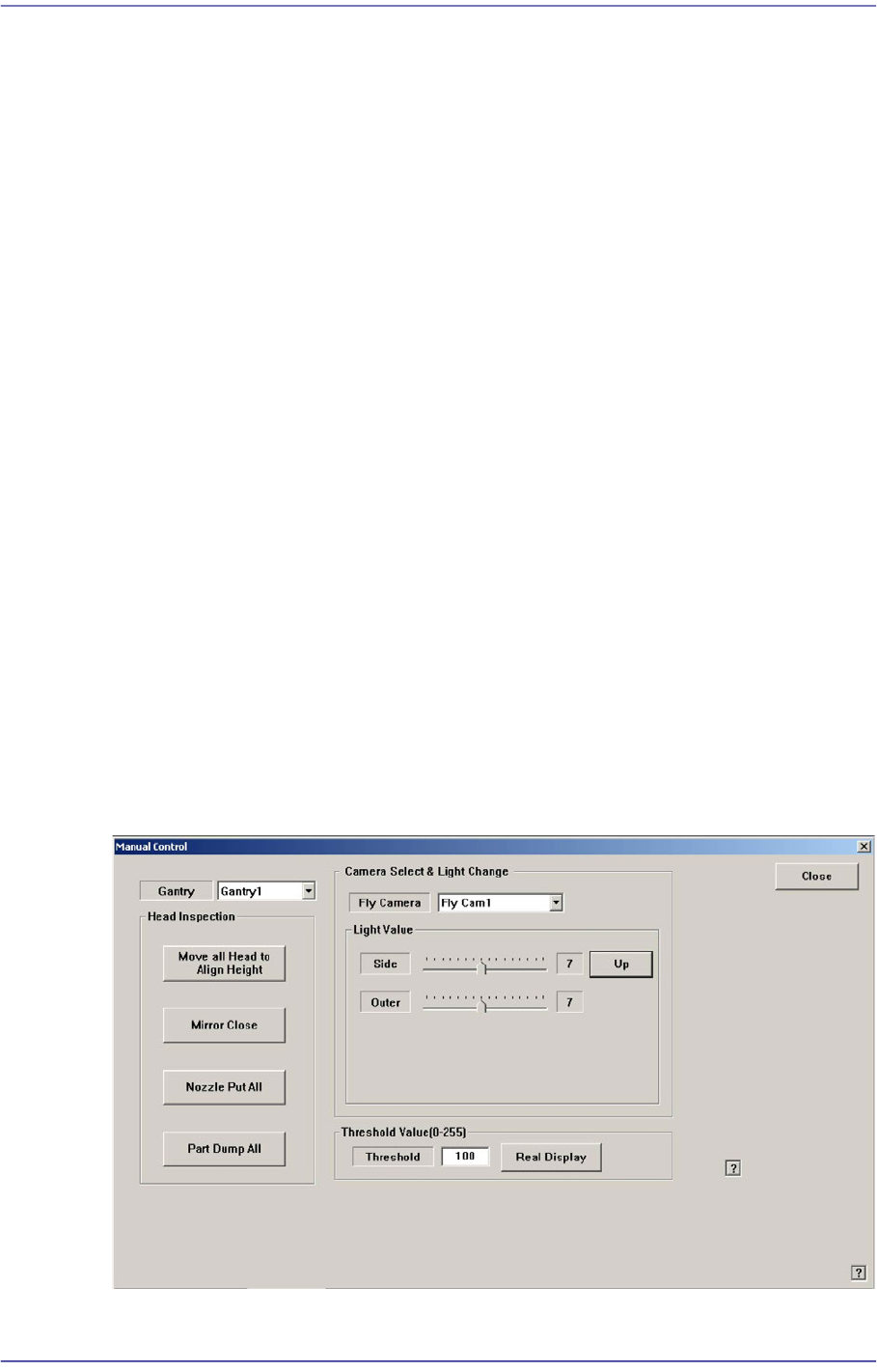
Performs setup of camera lighting or check of head operation by manually recognizing
parts with vision system.
Figure4.8 “Manual Control – Head” dialog box
4-22
Fast Flexible Placer SM481(L) PLUS Administrator’s Guide
<Gantry> combo box
Select the gantry to which the head to be tested belongs.
<Head Inspection> group
<Move all head to align height> button
Put the nozzle tip of the head at the align height for parts recognition.
<Mirror Open/Close> button
Open or close the mirror for parts recognition.
<Nozzle Put All> button
Return all nozzles placed at the head to the ANC.
<Part Dump All> button
Dump all the picked up parts at the dump box.
<Camera Select & Light Change> group
Set the illumination value of the fly camera. Select the fly camera whose illumination
is to be adjusted and adjust the slide bar in the <Light Value> group to adjust the
brightness.
<Threshold Value[0-255]> group
Images seen through SMVision consist of each pixel. In accordance with the
brightness, each pixel has a unique value ranging between 0 and 255. Here, ‘Threshold
Value’ signifies the border value determining whether each pixel should be recognized
in white or black. In the above figure, MMI is setup to be recognized as white when
the value is 100 or higher, and black when the value is less than 100.
<Real Display/Binary> button
Shows the image seen through SMVision in real display as seen by the naked eye
or binary image recognized by MMI.
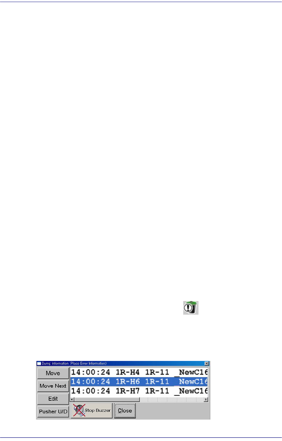
4.8. Dump Information (Place Error Information)
Used for confirming the message window indicating the contents on the abandoned parts
by placement error and feeder.
Figure4.9 “Dump Information (Place Error Information)” dialog box