Hanwha SM481 PLUS Series Administrator’s Guide Eng.pdf.pdf - 第292页
10-2 Fast Flexible Placer SM481(L) PLUS Administ r ator’s Guide <Arranged Feeder (s)> list box <FDLane> column The number in []is th e fe eder base number . The fe eder lane number wit h F i n front is Fr…
10-1
Optimization
Chapter10. Optimization
The Optimizer automatically creates a program to maximize the production efficiency by
optimizing the arrangement position and operation order of tape feeder, nozzle, ANC, and
others. The method to achieve the maximum production efficiency is as follows;
The balance between Gantries
Minimize the number of nozzle changes
Maximize the number of simultaneous pickups by the feeder
Arrange the feeders so that the time for XY gantry movement is minimized
Decide the order of optimum mounting operation
The Optimizer takes into account of various operation conditions and executes the
optimum algorithm to achieve these results. In this chapter, the structures of various
setting screens and setting methods necessary to execute the Optimizer are explained.
10.1. Tape Feeder
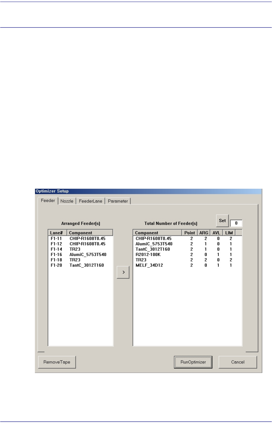
Figure10.1 “Optimizer Setup: Feeder Arrangement” dialog box
A window to set the optimum arrangement of tape feeders. Optimizer can arrange Tape
feeders on the optimum feeder lanes automatically in consideration of simultaneous
pickup and operation time. However, the user must specify mounting positions for Tray
Feeders and Stick Feeders.

10-2
Fast Flexible Placer SM481(L) PLUS Administrator’s Guide
<Arranged Feeder(s)> list box
<FDLane> column
The number in []is the feeder base number. The feeder lane number with F in front
is Front Feeder Base and that with R in front is Rear Feeder Base.
<Component> column
Displays the component name of the tape feeder mounted on the corresponding
lane. This list displays already arranged feeders. As these feeders are not arranged
arbitrarily by Optimizer, they affect arrangement of other feeders by Optimizer.
In other words, if there are feeders already arranged, the Optimizer arranges other
feeders to increase simultaneous pickups in consideration of these.
For the tape feeders of those indicated here, which are desired to be arranged
optimally by the optimizer, click the arrow button ( ) to move then to the right
list box and execute the optimizer.
All arranged tape feeders can be removed by pressing the <Remove Tape> button
under the dialog box..
<Total Number of Feeder(s)> list box
For each feeder, the number of placement points, the number of arranged tape feeders,
and the number of tape feeders to be newly arranged are displayed in the list box on
the right and can be viewed at a glance.
<Component> column
The components to be supplied from tape feeders are all displayed here.
<Point> column
Displays the number of placement points for each component. This can be referred
to when deciding the number of feeders to be mounted.
<ARG> column
Displays the number of feeders already arranged on the feeder lane for each
component. This number coincides with the number of feeder lanes shown in the
list box on the right.
<AVL> column
Displays the number of feeders to be arranged by Optimizer for each component.
<LIM> column
Displays the sum of the feeders shown in ARG and AVL for each component. In
other words, it is the limited number of feeders that can be arranged for each
component. The minimum value is 1.
<Set> button
Used to specify the number of feeders to be arranged for each component. When there
is one feeder already arranged for a certain part, enter ‘3’ in the right edit box and click
10-3
Optimization
this button. Then the number of <AVL> column becomes ‘2’.
Appropriate number of feeders must be set in consideration of the number of
placement points for each component. If the Optimizer considers that more than one
feeders are not necessary, it might not be used. .
To obtain good operation efficiency, a relatively large number of feeders must be
assigned to a component with many placement points.
button
Used to have the feeder selected in the <Arranged Feeders> list box to be arranged
again by Optimizer.
10.2. Nozzle
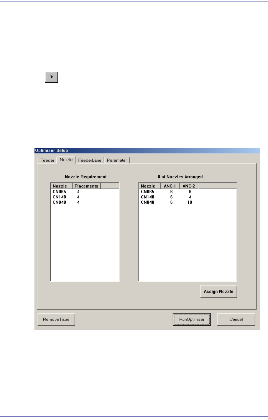
Figure10.2 “Optimizer Setup: Nozzle” dialog box
This dialog box shows the information on Nozzle arrangement.
<Nozzle Requirement> list box
This list box indicates the types of nozzles necessary for the part placement as well as
the number of times of use of each nozzle.
<Nozzle> column
Displays the nozzle name.