Hanwha SM481 PLUS Series Administrator’s Guide Eng.pdf.pdf - 第445页
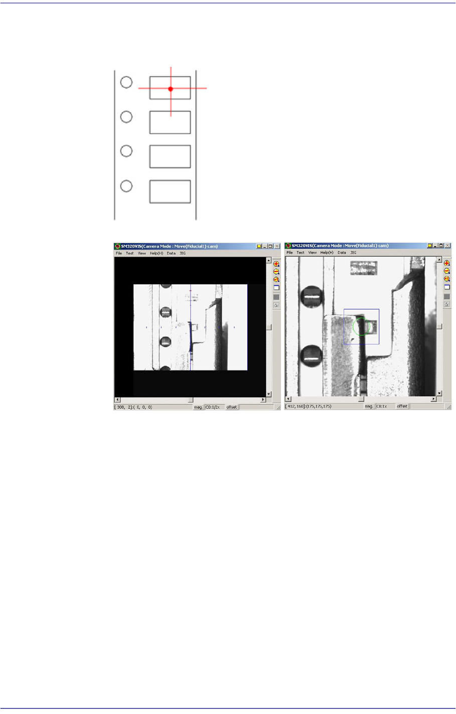
15-9 System Setup 4. Perform t e aching t he picku p point of the tape f eeder using ‘F i ducial C a mera’. At this tim e, teach the center point as in the figure. T ea ching must be done on the cen ter of the pocket, no…
15-8
Fast Flexible Placer SM481(L) PLUS Administrator’s Guide
15.2. Position [F4]
Sets various origins of the equipment and the position of the system dump box.
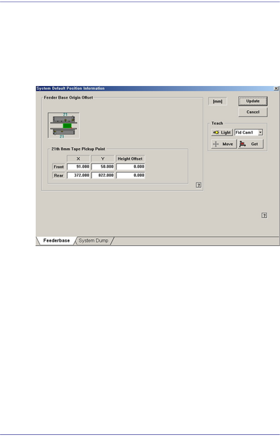
15.2.1. <Feeder base> tab dialog
Sets origin of each component of the equipment.
Figure15.5 “Feeder base” tab dialog
<Feeder Base Origin Offset> group
Sets feeder base related data.
<21th 8mm Tape Pickup Point> edit box
Sets the origin of the Feeder Base.
Method of setting up the ‘Feeder Base Origin’ is as follows;
1. Place reel of the smallest part (0603, 1005) and install in the 21st slot of the
front feeder base.
Before installing the feeder, be sure to check if there is any abandoned part on
the feeder base. Remove if any.
2. Select the <21st 8mm Tape Pickup Point> edit box with the mouse and select
‘Fid Cam’ in the Combo Box of the <Teach> area.
3. By clicking on the <Move> button, move the fiducial camera to the pickup
point of the tape feeder installed in the 21st slot of the front feeder base.
15-9
System Setup
4. Perform teaching the pickup point of the tape feeder using ‘Fiducial Camera’.
At this time, teach the center point as in the figure. Teaching must be done on
the center of the pocket, not on the center of the part.
5. Fit the center of the cross lines of ‘Fiducial Camera’ indicated in the
SMVision window to the pocket center, and input the value of the present
coordinates to the selected edit box by clicking on the <Get> button.
6. In the same way, install the feeder in the 21st slot of the rear feeder base, and
perform teaching.
<Height Offset> edit box
Set the Z value of the feeder base origin.
15-10
Fast Flexible Placer SM481(L) PLUS Administrator’s Guide
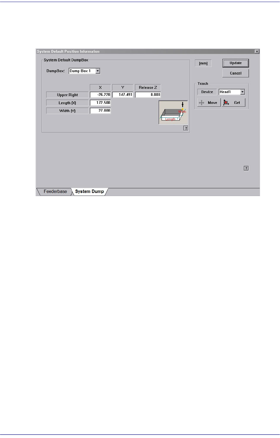
15.2.2. <System Dump> tab dialog
Sets the data related to the dump box where picked components are dumped.
Figure15.6 “System Dump” tab dialog
<System Default Dump Box> group
Inputs the position of the system dump box.
<Dump Box> combo box
Select the dump box to be set.
<Position - X, Y> edit box
Sets the X and Y positions of the head when dumping the components. Teach the
position (dump box center) at which parts are dumped.
<Release Z > edit box
Sets the Z axis of the head spindle when dumping parts.
<Length [X] > edit box
Inputs the dump box length.
<Width [Y] > edit box
Inputs the dump box height.
<Update> button
Transmits the set data to the equipment and closes the dialog box.
<Cancel> button
Ignores the set data and closes the dialog box.