Hanwha SM481 PLUS Series Administrator’s Guide Eng.pdf.pdf - 第188页
7-30 Fast Flexible Placer SM481(L) PLUS Administ r ator’s Guide 1: Length of the r e cta ngle in the X dir ec ti on 2: Length of the r e cta ngle in the Y dir ec ti on 3: Spacing in the X dir ection - bilateral symmetry …
7-29
Part Registration
1: Length of the rectangle in the X direction
2: Length of the rectangle in the Y direction
3: Spacing in the X direction - bilateral symmetry
- :When the outer frames of bright shapes on the right and left are
unclear
Shape definition - Lead (Coil Type2)
1: Length of the rectangle in the X direction
2: Length of the rectangle in the Y direction
3: Spacing in the X direction - bilateral symmetry
- :When the inner frames of bright shapes on the right and left are
unclear
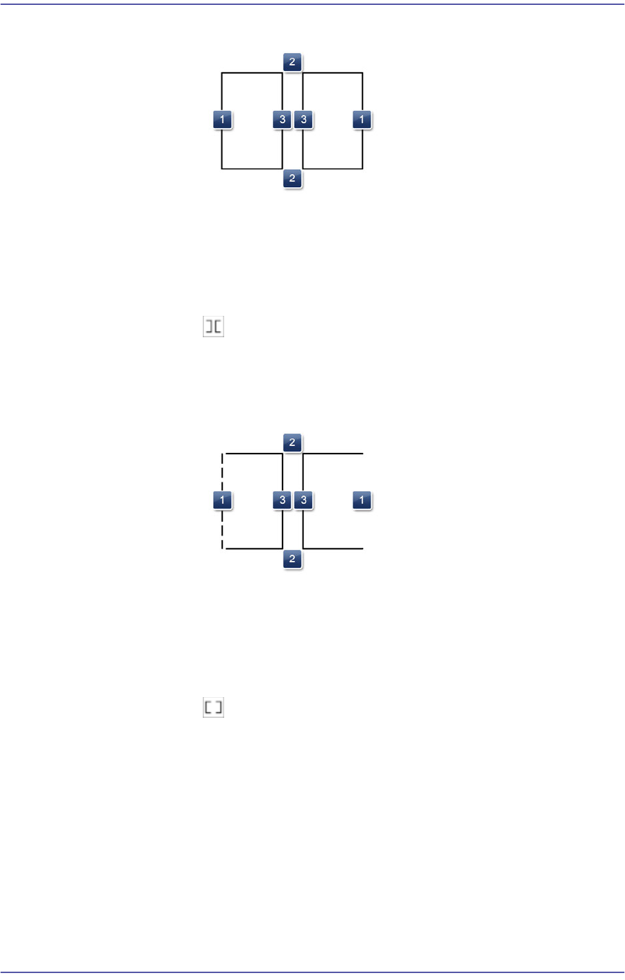
Shape definition - Lead (Coil Type3)
7-30
Fast Flexible Placer SM481(L) PLUS Administrator’s Guide
1: Length of the rectangle in the X direction
2: Length of the rectangle in the Y direction
3: Spacing in the X direction - bilateral symmetry
- :When the central shape of the part is recognized clearly
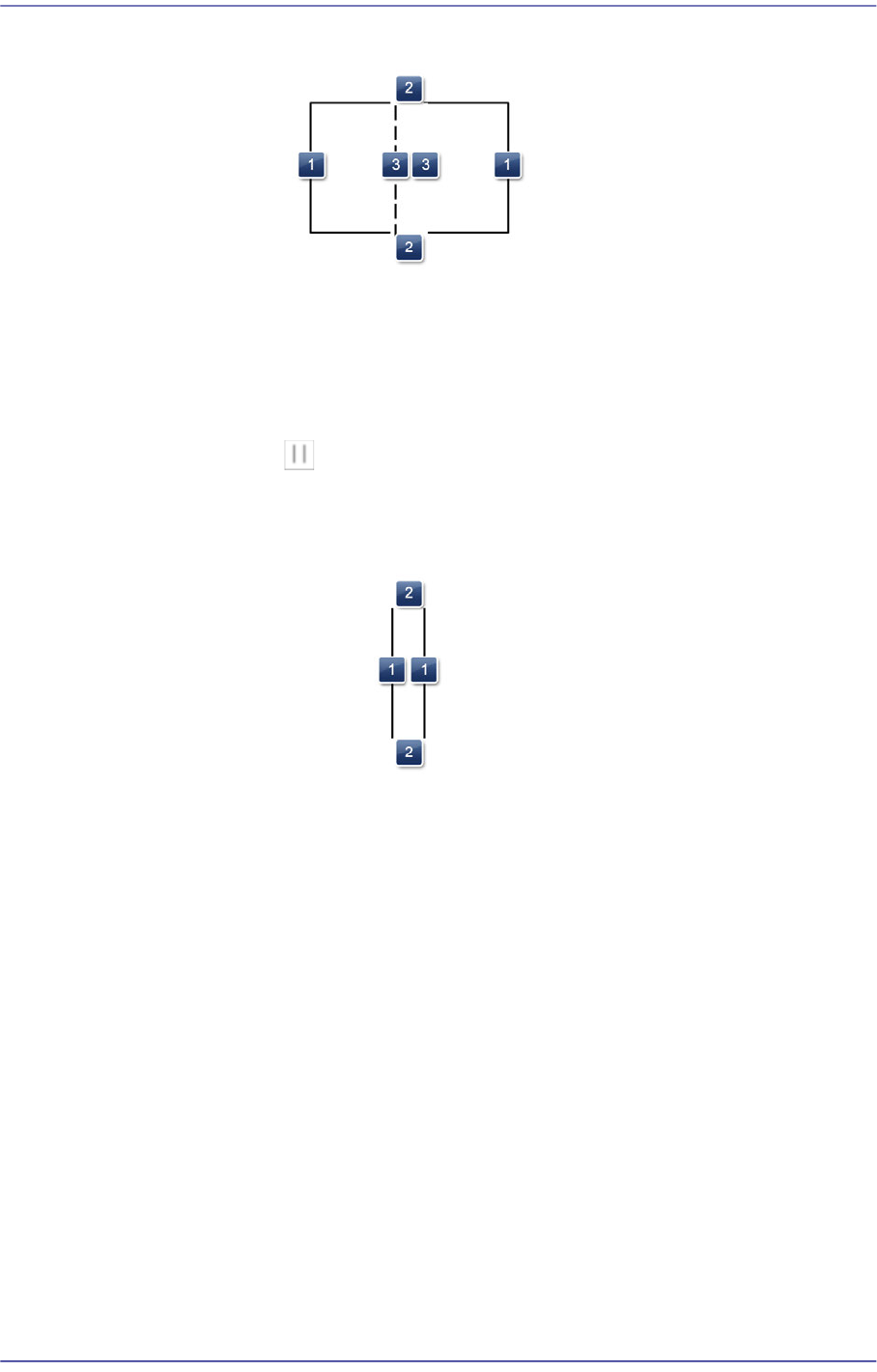
Shape definition - Lead (Coil Type4)
1: Spacing in the X direction
2: Line length in the Y direction - bilateral symmetry
When the lead is of electrode type.
Since it is applied to a rectangular chip part, the shape is fixed as a
rectangle.
<Count/Count XY> edit box
When the lead is of Gull Wing, J Lead and Land type, sets the number of leads
on the selected object.
When the leads exist above/below the body center, input the number of leads
which exist in the X direction. (SOP, SOJ)
When the leads exist at the left and right of the body center, input the number
of leads which exist in the Y direction. (SOP2, SOJ2)
When the leads exist in four directions from the body center, input the number
of leads which exist in the X and Y directions. (QFP, PLCC)

7-31
Part Registration
<Position> combo box
When the lead is of Gull Wing, J Lead and Land type, selects the direction in
which the lead selected from the body center.
However, this menu is disabled when the selected object is a lead group.
Left / Right / Up / Down
<Pitch/ Pitch XY> edit box
Sets the distance between leads when the selected object is a lead group.
When the leads exist above/below the body center, input the lead interval in
the X direction.
When the leads exist at the left/right of the body center, input the lead pitch in
the Y direction.
<Foot> edit box
When the lead is of Gull Wing, J Lead and Land type, input the length of the
area where the lead comes into contact with the solder on the upper surface of
the PCB.
<X/ Y> edit box
Input the X and Y offsets between the vision window center and the center of
the selected object.
<Width> edit box
Input the width of an object to suit the image of an actual part. If the selected
object is round, input the diameter.
<Height> edit box
Input the height of an object to suit the image of an actual part. Only when the
selected object is rectangular is this enabled.
<Tolerance %> edit box
Even though there will be a difference between the recognized part shape and
the shape object of the registered part, input the allowable level as a
percentage.
For example, if the tolerance is set to 10%, the data of the registered shape
object is 10 and the shape data of the actually recognized part is 11, the vision
system considers that the shape of the recognized part is a normal shape.
In order to set detailed tolerance by major recognition parameter, click the
<Detail> button at the right.
<Detail> button
Sets the over-tolerance and under-tolerance for the length, width, foot and
pitch, respectively.
Over-tolerance: Allows the tolerance to exceed the set value