Hanwha SM481 PLUS Series Administrator’s Guide Eng.pdf.pdf - 第376页
14-24 Fast Flexible Placer SM481(L) PLUS Administ r ator’s Guide 14.3.1. Axis Home Calibration Sets the limit position of each axis to move. When thi s button is clicked on, the following dialog box is displayed. Figure1…
14-23
Machine Calibration
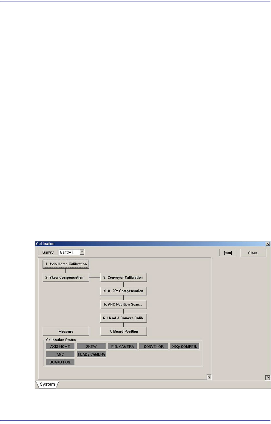
14.3. Calibration [F9]
Only fix camera is activated. Used for setting up the position of the fiducial mark of the fix
camera located at the upper part of ANC.
The following are the works to be performed before performing calibration or those to be
performed in advance.
I/O Test
Mirror offset check and correction
Nozzle check and vacuum check option for system constant
ANC type check
Pneumatic system check for any problem
The order in which the calibration is performed and the calibration tool needed to perform
the corresponding calibration is as follows;
Axis Home Calibration
Skew Compensation
Fiducial Camera Scale Calibration
Conveyor Calibration
X-XY Compensation – Calibration Bar
ANC Fiducial Mark Teaching
Head & Camera Calibration - CN040, CNT20, Light Fly Nozzle, Calibration Tool
14-24
Fast Flexible Placer SM481(L) PLUS Administrator’s Guide
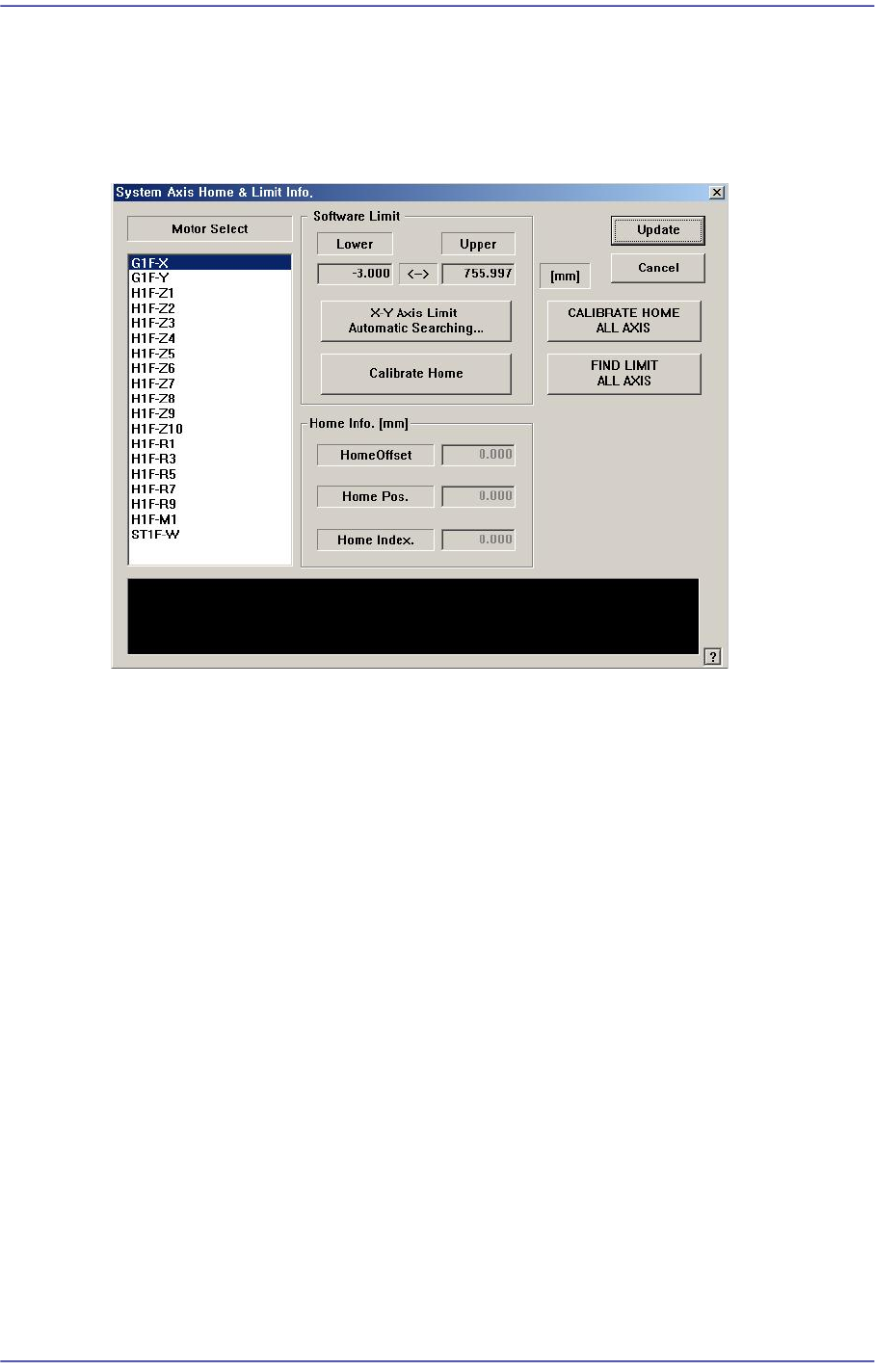
14.3.1. Axis Home Calibration
Sets the limit position of each axis to move. When this button is clicked on, the following
dialog box is displayed.
Figure14.8 “System Axis Limit Info.” dialog box
<Motor Select> list box
Select the motor axis for which to set the limit. Available axes are as follows.
G1F-X: X axis of the front gantry
G1F-Y: Y axis of the front gantry
H1F-Z1: Z axis of head1 of the front gantry
H1F-Z2: Z axis of head2 of the front gantry
H1F-Z3: Z axis of head3 of the front gantry
H1F-Z4: Z axis of head4 of the front gantry
H1F-Z5: Z axis of head5 of the front gantry
H1F-Z6: Z axis of head6 of the front gantry
H1F-Z7: Z axis of head7 of the front gantry
H1F-Z8: Z axis of head8 of the front gantry
H1F-Z9: Z axis of head9 of the front gantry
H1F-Z10: Z axis of head10 of the front gantry
H1F-M1: Mirror axis of the front gantry
H1F-R1: Theta axis (H1, H2) of the front gantry
H1F-R3: Theta axis (H3, H4) of the front gantry
14-25
Machine Calibration
H1F-R5: Theta axis (H5, H6) of the front gantry
H1F-R7: Theta axis (H7, H8) of the front gantry
H1F-R9: Theta axis (H9, H10) of the front gantry
ST1F-W: Width control motor of the front work station(F2)
<Software Limit> group
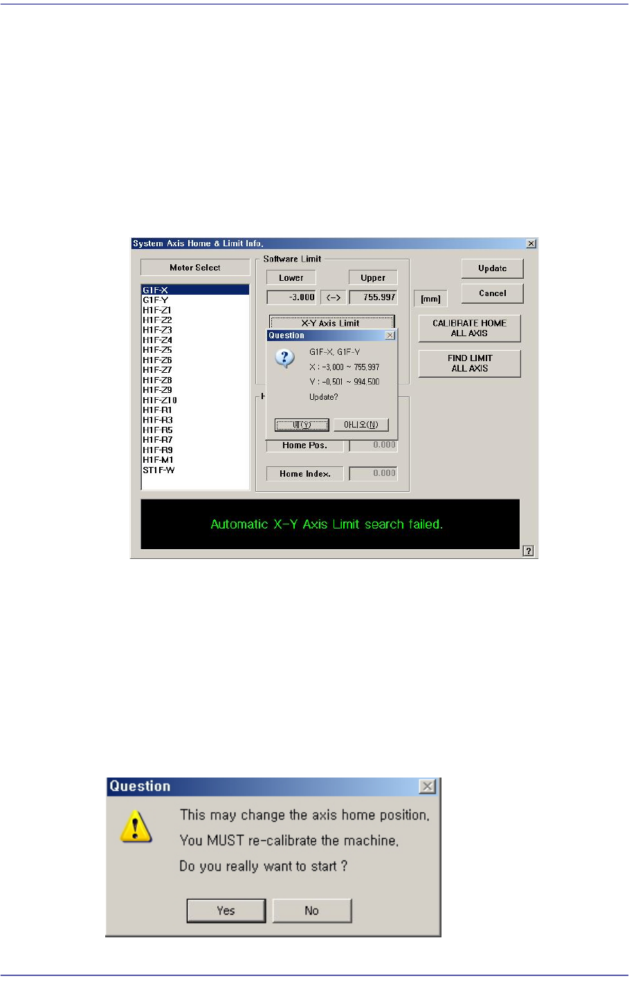
<X-Y Axis Limit Automatic Searching…> button
Finds the limit of the X and Y axes automatically and checks whether to apply the
changed value.
<Skew Compensation> button
Activated when selecting the Y axis. It is used to perform the skew compensation. For
further details, refer to “12.3.2 Skew compensation”.
<Calibrate Home> button
Automatically finds and reflects the home position of the motor selected from the
<Motor Select> list box.
<CALIBRATE HOME ALL AXIS> button
Automatically finds and reflects the home positions of all axes.