Hanwha SM481 PLUS Series Administrator’s Guide Eng.pdf.pdf - 第298页
10-8 Fast Flexible Placer SM481(L) PLUS Administ r ator’s Guide <Array Options> group Used when desi gn ate display method and optimiza tion option of the MMI step program whe n editing the array PCB. <Exten…
10-7
Optimization
button ( ) to move it to the <Prohibited> list box group.
The optimizer arranges no device in the feeder base slot indicated in the <Prohibited>
list box. Clicking the arrow button ( ) can undo the command.
The optimizer arranges the devices considering the interference between the devices
that are arranged as feeder base slots or which will be newly arranged.
10.4. Setup Menu /Parameters
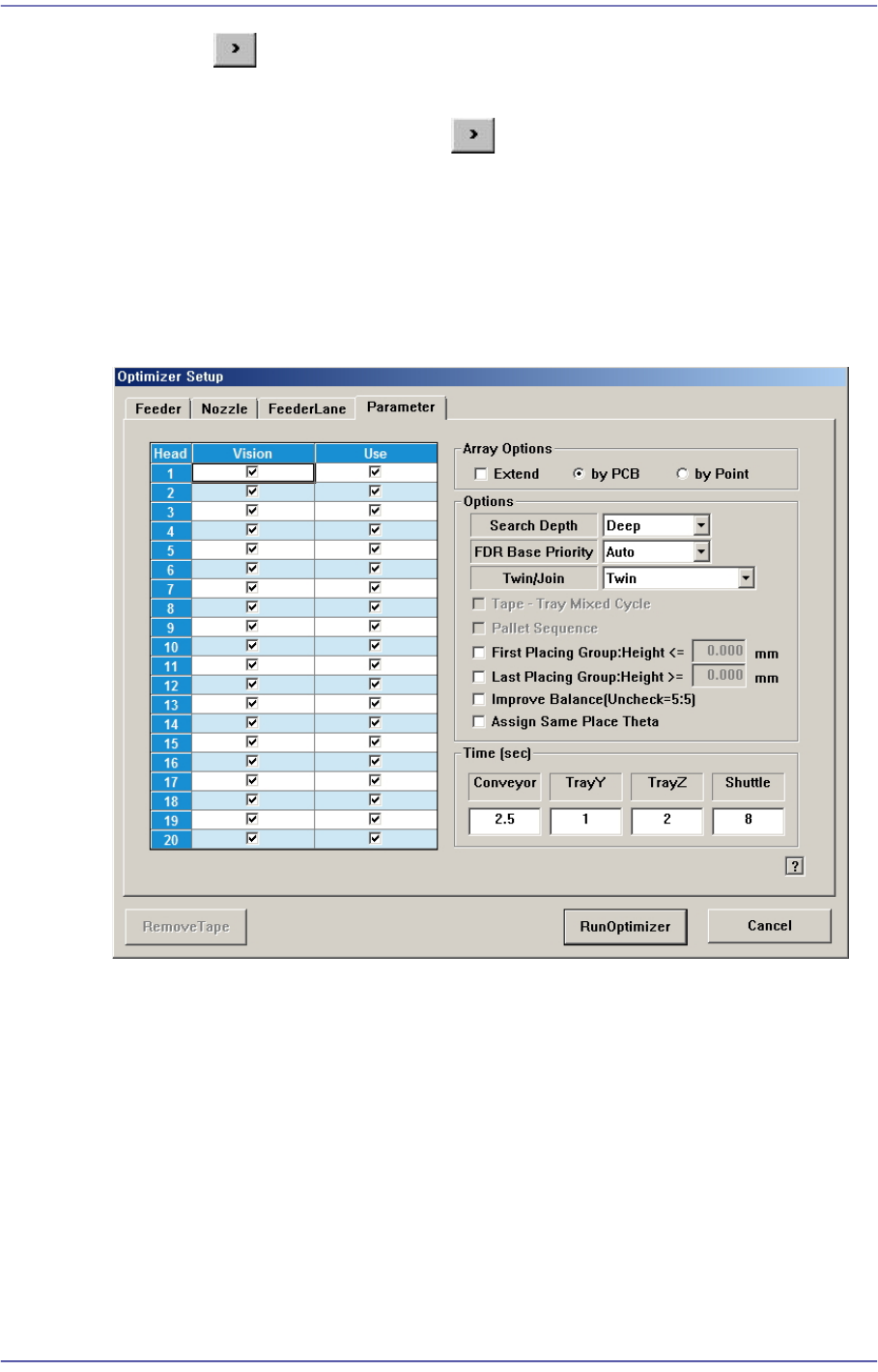
Figure10.5 “Optimizer Setup: Parameters” tab dialog box
This dialog box to set the options and parameters for the Optimizer execution.
<Head> check box group
Sets whether to use for each head.
<Use> check box
The “Use check box” indicates whether to use the corresponding head. For
example, when it is difficult to perform work if Head 3 has a problem, select the
check box of Head 3 and leave it blank.
Doing so, the optimizer will create a job program with the head except for the one
whose use is suspended. If all heads to be used are stopped, the optimizer cannot
perform optimization.

10-8
Fast Flexible Placer SM481(L) PLUS Administrator’s Guide
<Array Options> group
Used when designate display method and optimization option of the MMI step
program when editing the array PCB.
<Extend> check box
In case of array PCB, <Extend> check box can be ticked. Then, MMI performs
optimization considering one array PCB includes all the array installation
positions. Accordingly, work efficiency is improved.
When the <Extend> check box is not selected, selection of either “By PCB” or
“By Point” is possible.
<By PCB> option button
Creates the step program so that the optimizer performs optimization only for one
small PCB and performs work for several small PCBs in order.
<By Point> option button
Performs work in order on the second placement point of the first array after
finishing the work on the first placement point of the array, the first placement
point of the second array, and the first placement point of the last array.
Generally, when many nozzles are replaced, it is efficient to perform work in the
manner applying ‘By Point’.
However, work efficiency may be lowered if there are many defective unit PCB’s.
<Options> group
Sets the selection condition for the optimizing algorithm executed by the optimizer.
<Search Depth> combo box
Select the level at which the placement sequence is optimized.
Quick
Optimizes the placement sequence based on the nearest placement point. In
this method, the time required for the optimization is relatively short.
Deep
The optimizer compares all possible placement cases for all placement points
to determine the optimum placement sequence. In this method, the time
required for the optimization is relatively long.
<FDR Base Priority> combo box
Enables to give priority while the optimizer arranges feeder.
Auto
The optimizer arranges the feeder automatically.
Front
The optimizer arranges the feeder of the front feeder base first.
10-9
Optimization
Rear
The optimizer arranges the feeder of the rear feeder base first.
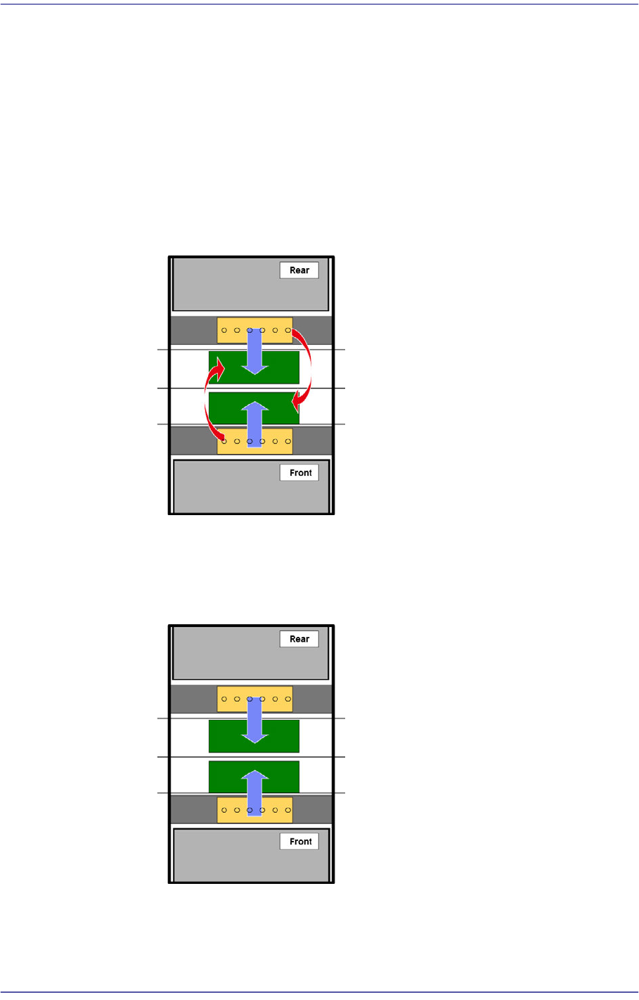
<Twin/Join> combo box
Prioritize the gantry to place parts on a PCB loaded to the conveyor.
Join
Selected when producing the same models at the front and rear in small
quantity. Since it is possible to use the front and rear feeder together, this
mode can be used when performing production by installing a small quantity
of feeders.
Twin
Selected when producing the same models at the front and rear in large
quantity. Since feeders must be installed at the front and rear, many feeders
must be installed.
Join (Partial Twin)
Used when performing mixed production of the same model at the front and
rear in the join mode and twin mode.