Hanwha SM481 PLUS Series Administrator’s Guide Eng.pdf.pdf - 第453页
15-17 System Setup Select the device to be taught first from <Device> in the <T each> group and insert t he CN040 nozzle in the nozzle holder of the correspondin g head. Move the head to the dripping posi…
15-16
Fast Flexible Placer SM481(L) PLUS Administrator’s Guide
indicated.
The set value can be initialized by the submenu ‘Flux.’ of the ‘Product’ menu.
<Squeeze Warn Count> edit box
This is set for cleaning the flux module during automatic production. If the
corresponding count is reached, the warning message is indicated.
The set value can be initialized by the submenu ‘Flux.’ of the ‘Product’ menu.
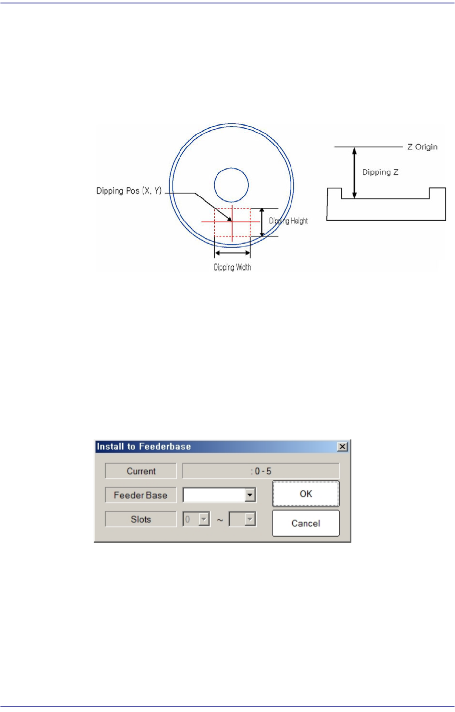
<Position> group
This is enabled when the <Use Flux Device> on the right is selected. Set the dripping
position. If the setup slot is determined at the feeder base of the flux module, the
dripping position is set automatically.
<X> edit box
Refers to the X coordinate of the dripping position.
<Y> edit box
Refers to the Y coordinate of the dripping position.
<Z> edit box
Refers to the Z coordinate of the dripping position.
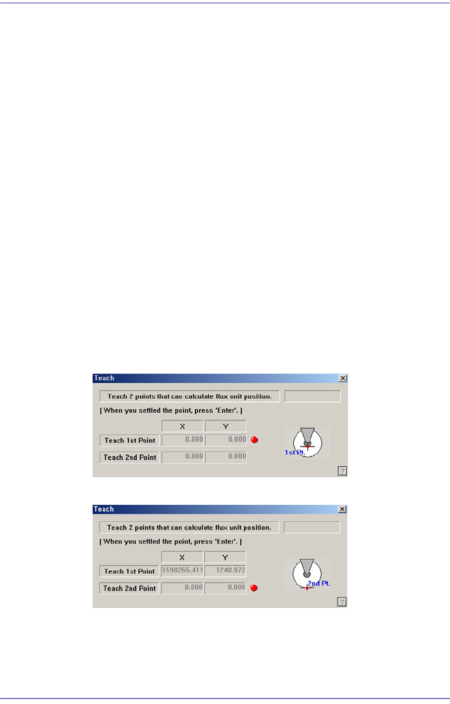
<Teach…X/Y> button
Execute the following dialog box to teach the XY coordinate of the dripping
position.
Set the first point correctly and press the ‘Enter’ key.
Set the second point correctly and press the ‘Enter’ key.
<Teach…[Z]> button
Teach the Z coordinate of the dripping position. The teaching procedure is as
follows:
15-17
System Setup
Select the device to be taught first from <Device> in the <Teach> group and
insert the CN040 nozzle in the nozzle holder of the corresponding head.
Move the head to the dripping position.
Move down the spindle of the head until it contacts the disk surface. If the
nozzle end contacts with the disk surface, the change in the pneumatic
pressure occurs and the Z axis position is taught automatically.
<Use Flux Device> check box
This check box is selected to set the item related to the flux module.
<Churning> button
If this button is selected, the disk of the flux module rotates.
<Not Usable Lane> group
It sets the item related to the operation of the flux module.
<Feeder Base> button
Selects the feeder base on which the flux module is to be installed.
15-18
Fast Flexible Placer SM481(L) PLUS Administrator’s Guide
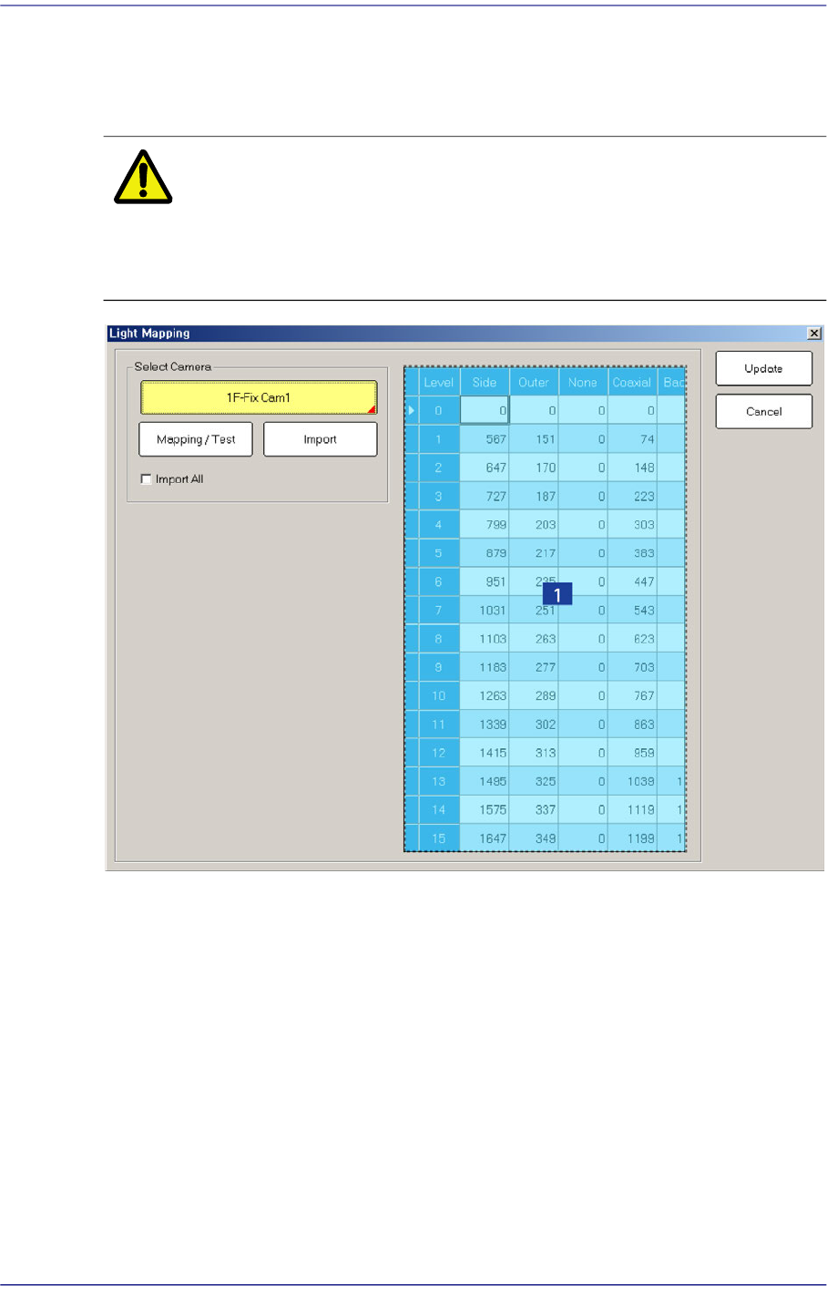
15.4. Light Mapping
Calibrate the brightness of the light for the camera. In order to perform this calibration,
insert the LightFly or LightFix into the No. 1 nozzle of the ANC.
Caution Since the nozzle for the SM32x,SM411, SM421 model is
not compatible to the one for the light mapping used for the
SM32x,SM411, SM421 model, do not use it for this
machine.
1: Light Level group
<Select Camera> combo box
Selection Control
Select the camera to perform light mapping.
Repeat this procedure for all fly cameras and fix cameras.
Light Level group
Sets the brightness by light level.
<Level> column
Dislays 16 steps of lighting.
<Side>/ <Outer>/ <Coaxial> column