Hanwha SM481 PLUS Series Administrator’s Guide Eng.pdf.pdf - 第129页
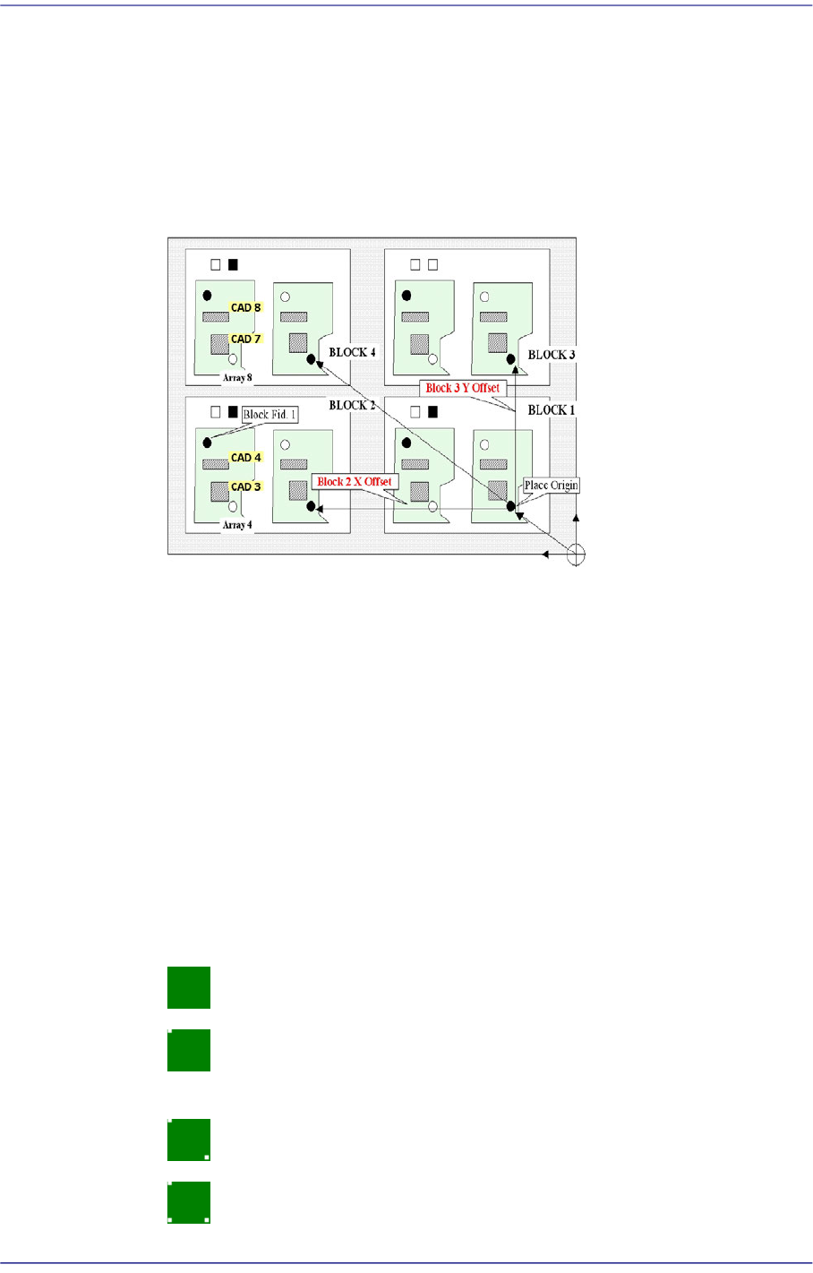
6-19 Board Definition points are used selectively when compensatin g the distortion of the X, Y or R coordinate of the PCB. 4 Panel: 4 fiducial marks for PCB correction. 1 Array: 1 fiducial mark for Array PCB correct…
6-18
Fast Flexible Placer SM481(L) PLUS Administrator’s Guide
<Block Select> combo box
For a Multi PCB
The model selected from the “Board Definition” dialog box is selected
automatically and the corresponding Combo Box is disabled.
For a Block PCB
Select the model for which setup will be performed and set other items.
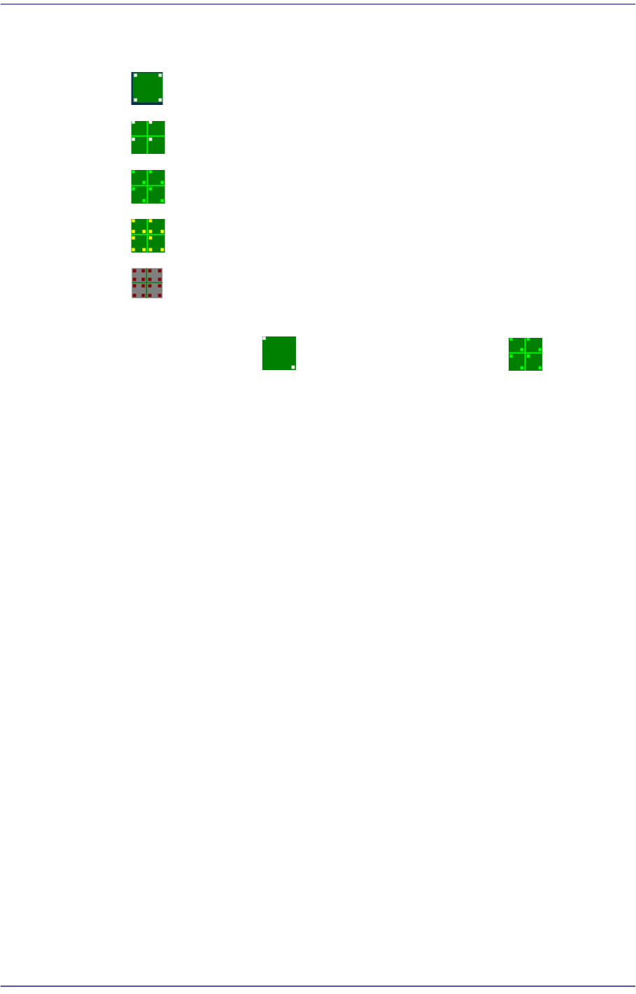
<1. Position Type> combo box
One, two or three fiducial marks can be selected for use.
When one fiducial mark is selected, the X and Y distortion can be corrected. However,
it is difficult to correct the theta angle.
That is, it is used if the external machined section of the PCB is very precise or when
there is only one fiducial mark inevitably. Generally, 1 point fiducial is not used.
In the case of 2 fiducial marks, the X, Y and theta of the PCB can be corrected. This is
the most frequently used method.
In the case of 3 fiducial marks, they are used when the deviation of the score value is
great because the surface of the fiducial marks is unstable. If 3 fiducial marks are used,
the machine can calculate the horizontal and longitudinal position more accurately.
Here, Select the number of fiducial marks. Available numbers are as follows.
None: Fiducial Mark.
1 Panel: In the case of one point, the distortion of the X or Y coordinate can
be compensated.
2 Panel: 2 fiducial marks for PCB correction.
3 Panel: In the case of three points, only two points that obtained higher
6-19
Board Definition
points are used selectively when compensating the distortion of the X, Y or R
coordinate of the PCB.
4 Panel: 4 fiducial marks for PCB correction.
1 Array: 1 fiducial mark for Array PCB correction in each Array PCB.
2 Array: 2 fiducial marks for Array PCB correction in each Array PCB.
3 Array: 3 fiducial marks for Array PCB correction in each Array PCB.
4 Array: Each Array PCB has 4 fiducial marks for the calibration of the
PCB board.
It is recommended to use two panels for a general PCB and two arrays for
an array PCB.
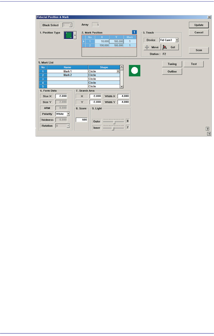
<2. Mark Position> group
If “None” is not selected in the <1. Position Type> combo box, data is created as many
as the number of the selected fiducial marks. For example, when “2 Panel” is selected,
the following dialog box is displayed.
6-20
Fast Flexible Placer SM481(L) PLUS Administrator’s Guide
Figure6.5 “Fiducial Position & Mark” dialog box (When the Position Type is “2 Panel”)
1: Grid Cell
<No> column
A serial number of the position of fiducial mark.
<X> column
The X position value of fiducial mark.
<Y> column
The Y position value of fiducial mark.
<Mark ID> column
The mark ID value of fiducial mark. This value must be set from a series of
numbers in <5. Mark List>.
<4. Teach > group
Used to teach the fiducial mark position.
<Device> combo box
Select the Camera for checking Fiducial Mark
Fid Cam2: Select the fiducial camera on the front gantry.
<Move> button
Move the object selected in the <Device> combo box to the position of the
assigned coordinates. Before executing <Move> button, the cell in the grid
(Coordinates of the fiducial mark) corresponding to the desired position must be
clicked on with a mouse.