Hanwha SM481 PLUS Series Administrator’s Guide Eng.pdf.pdf - 第324页
12-16 Fast Flexible Placer SM481(L) Administrator’s Guide <Assign Nozzl e> button Used to assign a pplicable h eads for each n ozzle s eparately . When this bu tton is clicked on, the following dialog box i s dis…
12-15
LED placement
12.4.3. Nozzle
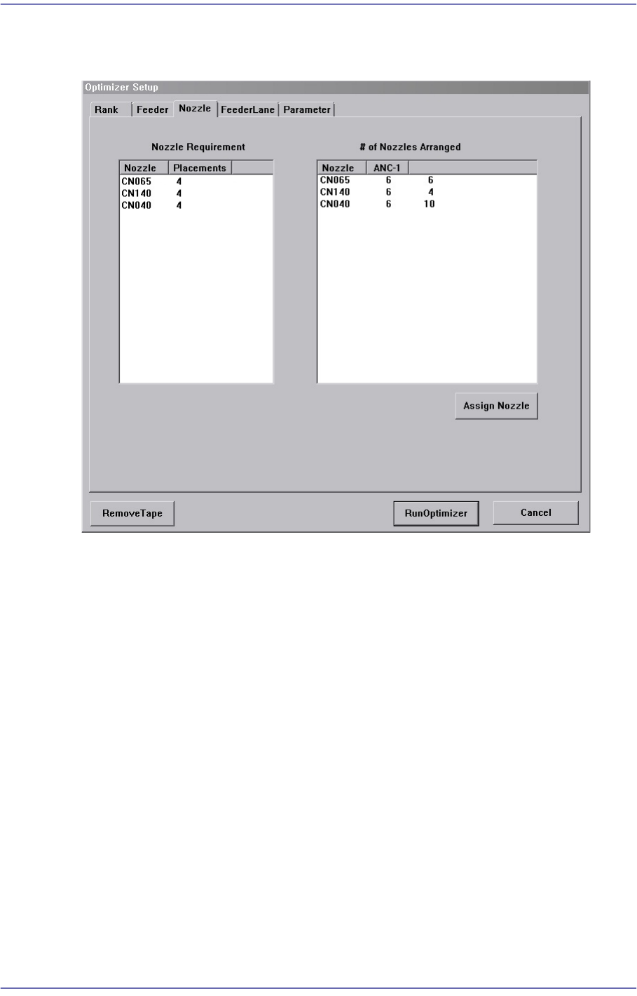
Figure12.5 “Optimizer Setup: Nozzle” dialog box
This dialog box shows the information on Nozzle arrangement.
<Nozzle Requirement> list box
This list box indicates the types of nozzles necessary for the part placement as well as
the number of times of use of each nozzle.
<Nozzle> column
Displays the nozzle name.
<Placements> column
Displays the number of times each nozzle is used. In other words, the number of
placement points using the corresponding nozzle.
<# of Nozzles Arranged> list box
This list box indicates the types and number of nozzles that are arranged in each ANC
currently.
<Nozzle> column
Displays the nozzle name.
<ANC-1 ANC-2> column
Displays the ANC where the nozzle is arranged.
12-16
Fast Flexible Placer SM481(L) Administrator’s Guide
<Assign Nozzle> button
Used to assign applicable heads for each nozzle separately. When this button is clicked
on, the following dialog box is displayed.
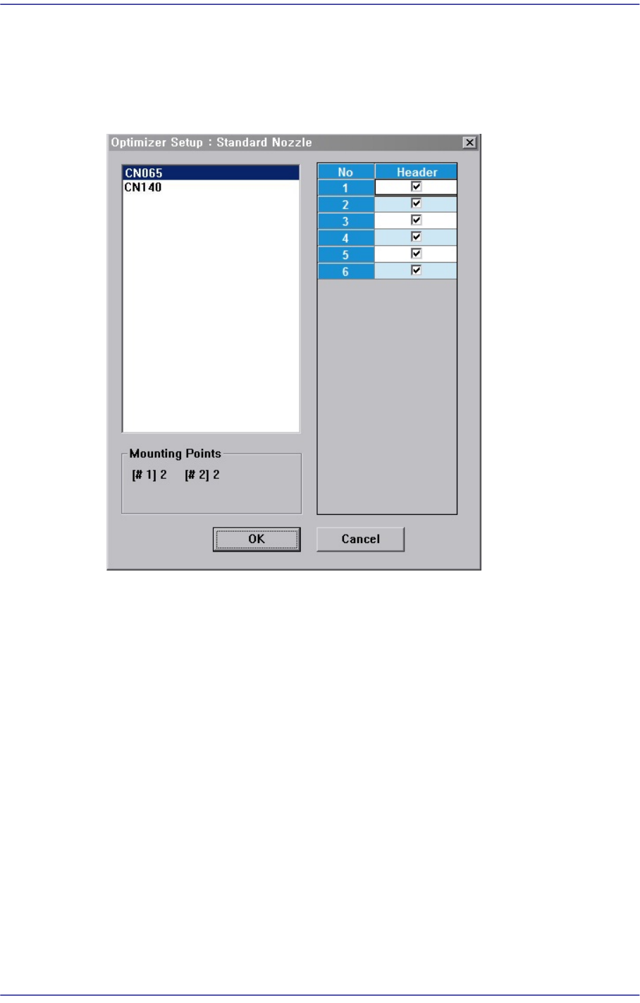
Figure12.6 “Optimizer Setup: Assign Nozzle” dialog box
Basically all nozzle types can be applied to any head, therefore all heads are checked.
But there are occasions when a certain nozzle has to be operated in a certain head.
Also, this can be used when the user wants to assign a certain head to a certain nozzle.
The above figure shows the nozzle CN040 can operate on any head between Head1
and Head2012610.
<Useful Heads> check box group
The heads that can be used by the selected nozzle type. As a standard, check so that
Head1 ~ Head2012610 can be used.
<Mounting Points> group
This group shows the number of components used by the nozzle selected for the
current PCB. This can be used as a reference data when the user assigns the applicable
heads to each nozzle.
#1 shows the total number of placement points of the component for which #1 nozzle
is selected and #10 shows the total number of placement points of the component for
which #10 nozzle is selected.
Figure 10-3 shows that CN040 is selected for 1# nozzle of three components and for

12-17
LED placement
2# nozzle of one component.
<OK> button
Saves the selected options and closes the dialog box..
<Cancel> button
Cancels the selected options and closes the dialog box.