Hanwha SM481 PLUS Series Administrator’s Guide Eng.pdf.pdf - 第470页
15-34 Fast Flexible Placer SM481(L) PLUS Administ r ator’s Guide 15.5.2. <Signal> tab dialog Set the status of the signal light. When t h i s button is selected, the following scr e en is displayed. Figure15.17 “Si…

15-33
System Setup
<Update> button
Transmits the change data to the equipment and closes the dialog box.
15-34
Fast Flexible Placer SM481(L) PLUS Administrator’s Guide
15.5.2. <Signal> tab dialog
Set the status of the signal light. When this button is selected, the following screen is
displayed.
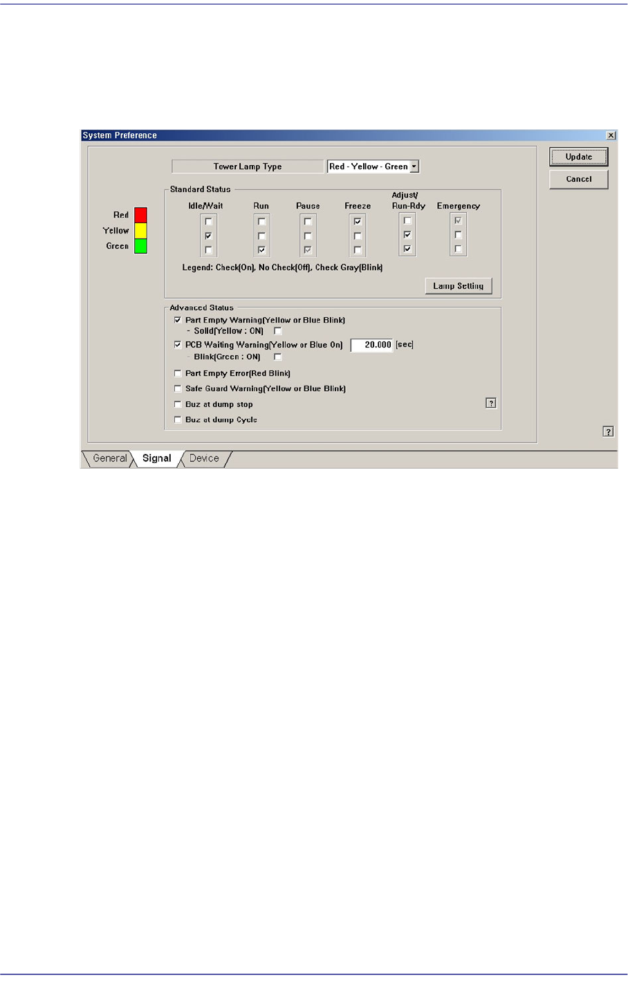
Figure15.17 “Signal” tab dialog
<Tower Lamp Type> combo box
Select the signal tower type. Available types are as follows.
Red –Yellow –Green: When the signal light consists of “Red –Yellow –Green”.
Red –Blue –Green: When the signal light consists of “Red –Blue –Green”.
<Standard Status> group
Set the status of the signal light corresponding to the equipment status.
For example, if you want to turn on the “Yellow” lamp of the signal tower in the idle/
wait status, check the corresponding “Yellow” lamp check box among the 3 check
boxes under the Idle/Wait.
The status and meanings of the check boxes are as follows.
Checked: Turns on the corresponding lamp.
Not checked: Turns off the corresponding lamp.
Checked in gray: Flickers the corresponding lamp.
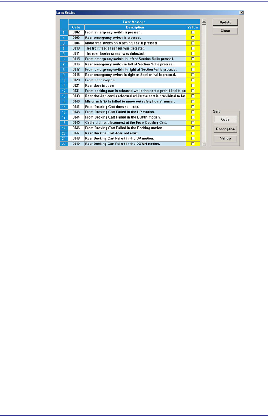
<Lamp Setting> button
The user can perform setup concerning the error by which the red lamp of the
signal light is turned on by default so that the yellow lamp is turned on selectively
according to the error type. Clicking this button will display the following dialog
box.
15-35
System Setup
If the red lamp is turned on, the equipment stops. Therefore, if the error can be
neglected according to the type of the error, select the corresponding error and
select the <Yellow> check box column.
<Advanced Status> check box group
<Part Empty Warning(Yellow or Blue Blink)> check box
Yellow lamp or blue lamp blinks when part empty alarm is emitted.
<Solid(Yellow: ON)> check box
If supplied parts are exhausted or an error occurs after the pickup retry count
has been exceeded, perform setup so that the yellow light (blue light) remains
turned on.
<PCB Waiting Warning(Yellow or Blue On> check box
If the equipment is ready for operation and has been waiting for a PCB to be fed
onto the conveyor longer than the time set here, the yellow or blue light is turned
on. To change the set time, use the edit box to enter the desired time period.
<Blink(Green: ON)> check box
If this checkbox is selected, the yellow light blinks and the green light is
turned on.
<Part Empty Error (Red Blink> check box
Red lamp blinks when ‘Part Empty’ error occurs.
<Safe Guard Warning (Yellow or Blue Blink> check box
Yellow lamp or blue lamp blinks when ‘Safe Guard Override’ function is released.
<Buz at dump stop> check box
If this check box is selected, the buzzer does not sound even though an error