Hanwha SM481 PLUS Series Administrator’s Guide Eng.pdf.pdf - 第396页
14-44 Fast Flexible Placer SM481(L) PLUS Administ r ator’s Guide 2. Then, after the head assembly moves to the designated position, mov e all Z axes down. At this time, remove all inserted nozzles m anually 3. “Then the …
14-43
Machine Calibration
<Gantry> combo box
Select the Gantry for performing Calibration
<Target Camera> combo box
Select the camera to set light value.
<Light…> button
Set the light value for the selected camera.
14.3.7.1. Fix Camera Scale Calibration
The fix camera calibration must be performed before performing fiducial camera offset
calibration.
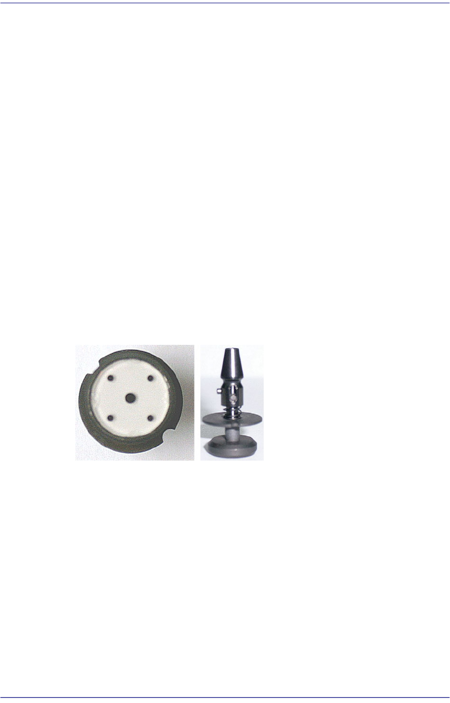
First, teach the fiducial mark on the upper surface of the fix camera and perform
calibration of the fix camera scale using the CNT20 nozzle.
<5. Fix 1 Camera> button
This calibration is performed to calibrate the Scale (um/pixel), Rotation (deg) and
Position (mm) of the fix-camera.
In order to perform this calibration first, the R-Offset Calibration must be performed in
advance and the calibration-nozzle must be used. Use Hole #1 as the ANC hole
exclusively used for the calibration-nozzle.
The following is the procedure to calibrate the Fix Camera Scale;
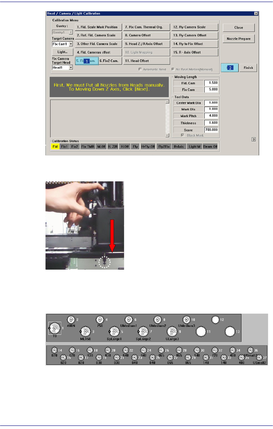
1. If the <5. Fix1 Camera> button is clicked, the message “First, We must Put all Nozzles
From Heads on Manually. To Move down Z Axis, Click [Next]” appears in the
message box. Click the <Next> button to move down the Z axis of the head in order to
manually move all nozzles inserted in the nozzle holder of the head.
14-44
Fast Flexible Placer SM481(L) PLUS Administrator’s Guide
2. Then, after the head assembly moves to the designated position, move all Z axes
down. At this time, remove all inserted nozzles manually
3. “Then the message “Next Attach the Calibration Tool to Head 1. Click [Next] for
Moving Down Head. After Moving, Attach the Tool to head Manually” appears. Click
the <Next> button after inserting the CNT20 nozzle at nozzle holder of Head #1
manually.
4. The message “Move To Center Position of Calibration Tool. To Move, Click
[Next].”appears. appears in the message window. Click the <Next> button to move the
head assembly to the calibration tool position on the ANC.
14-45
Machine Calibration
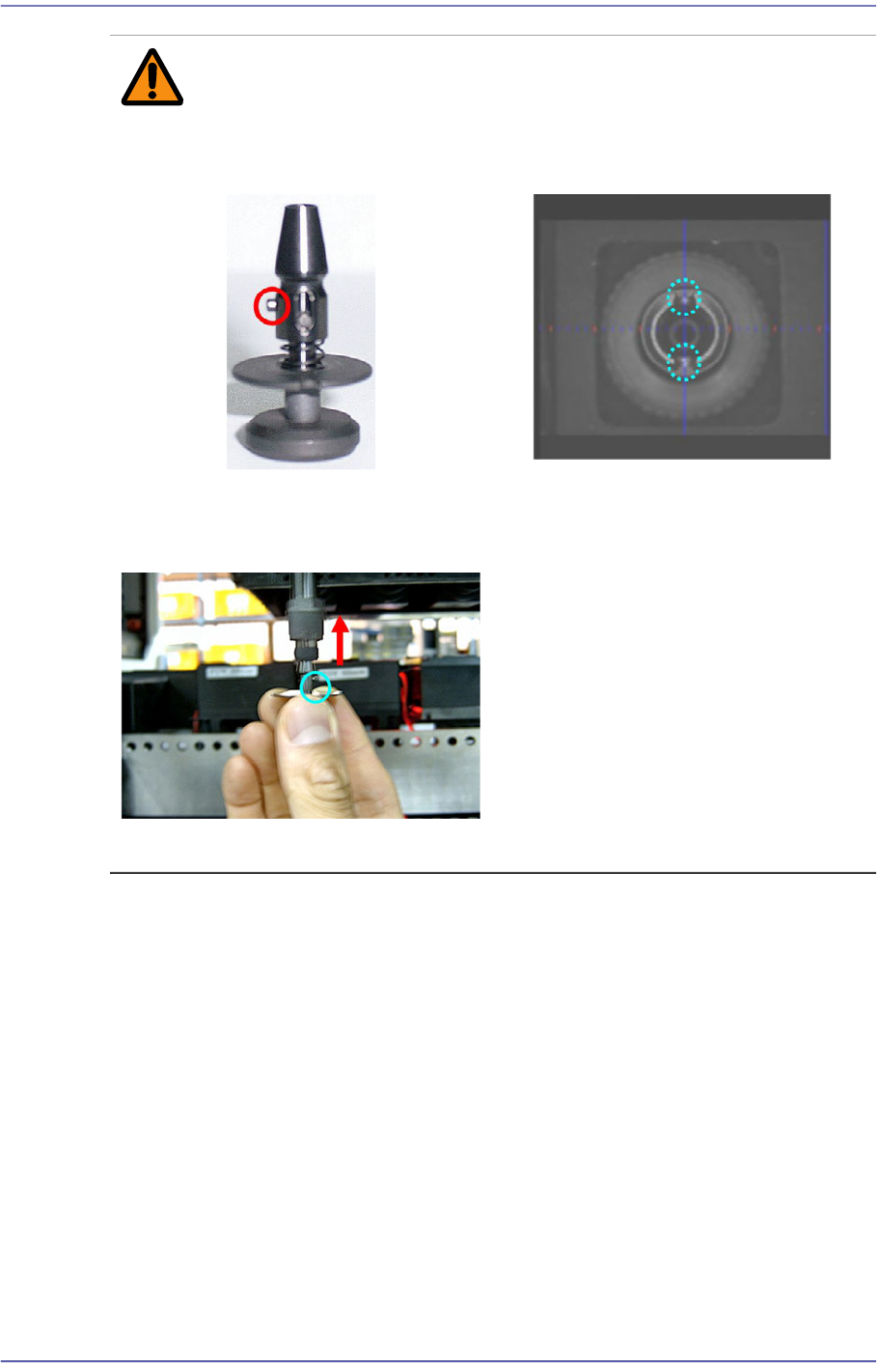
Caution Cautions to be taken when inserting the nozzle.
Insert the nozzle by referring to the following figure.
5. The message “Move To Center Position of [Fix1] Camera. To Move, Click [Next]”
appears in the message window. Click the <Next> button to move the head assembly
to the center of the fix-camera.
Direction Setup Pin of CNT20 nozzle
Direction Setup Groove of Nozzle
Holder
The CNT20 nozzle must be inserted
in the nozzle-holder so that the
direction-setup pin of the CNT20
nozzle is suitable for the direction-
setup groove of nozzle-holder.
Otherwise, an error may occur.