Hanwha SM481 PLUS Series Administrator’s Guide Eng.pdf.pdf - 第207页
7-49 Part Registration the position of the part to be picked up b y applying an of f set based on the part center . Selecting this selection box will set the X, Y a nd Z offse t s from the part c enter from the actual pa…
7-48
Fast Flexible Placer SM481(L) PLUS Administrator’s Guide
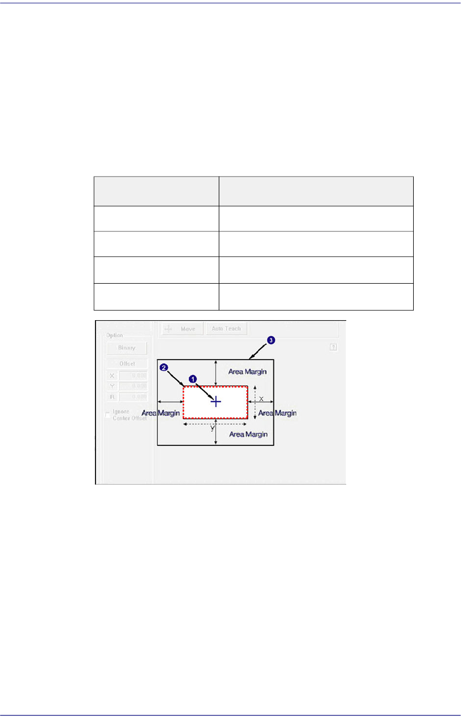
If the area obtained by adding the 'Recognition Area Margin' to the part size is
called the ‘Part Recognition Area’, in normal cases the shape of the picked part
must be within the ‘Part Recognition Area’.
However, even though the shape of the picked part has gotten out of the ‘Part
Recognition Area’ due to other external factors, if the part can be placed properly
by compensating the extent of deviation, it is possible to place the corresponding
part properly by setting the 'Recognition Area Margin'.
In general, set a value within the range of 0~6. For a chip part, it is recommended
that the default value be used.
1: Center of Mechanism
2: Area with a Recognition Area Margin of '0'
3: Part Recognition Area
<Recog. Threshold> combo box
The image viewed through the vision window consists of each pixel. Each pixel
has its own value from 0~ 255 according to the degree of viewed brightness.
Here, the 'Threshold' signifies the boundary value that distinguishes whether to
recognize each pixel as white or black.
<Center Offset> group
<Center Offset check> check box
When it is not possible to set the part center as a pickup point, it is possible to set
Part Size Recognition Area Margin
0402~1608 0.750
2012~3216 1.500
3216~□5mm
2.000
□5mm~□10mm
3.000

7-49
Part Registration
the position of the part to be picked up by applying an offset based on the part
center.
Selecting this selection box will set the X, Y and Z offsets from the part center
from the actual part pickup position.
For more details regarding part recognition option parameters other than those described
here, refer to “7.2.2.5.1. Recognition Option Setup by Part”.

7-50
Fast Flexible Placer SM481(L) PLUS Administrator’s Guide
7.2.2.5.1. Recognition Option Setup by Part
Describes the option related parameters allowing a part to be recognized under various
conditions by part.
Leadless Part (Chip)
Describes the recognition option applied to most of the leadless parts.
<Tolerance H(+)> edit box
In general, a part has a manufacturing tolerance. When the size of the recognized
part is larger than that in the registered part data, if its tolerance is not considered,
its inspection result will be no good.
Therefore, when recognizing a part, input the extent of the allowable difference
between the actual size and registered size as a percentage.
That is, when the value obtained by recognizing an actual part with the vision
system is greater than the input value, if the actual data value is allowed up to 1.3
times of the input data, the upper tolerance is 30%.
For the following chip parts, set the parameters referring to the following. For
other chip parts, it is recommended that the default value be used.
Chip-Circle
Tolerance is applied not to the length but to the area.
If a tolerance is applied to 10% of the diameter, the square of the diameter
must be applied. Therefore, apply 21% actually. (Tolerance (Over, Under)
=1.1´1.1=1.21 )
Chip-C 0402 /Chip-R 0402 /Chip-C 0603 /Chip-R 0603/ Chip-R 1005
Set the tolerance to be greater than the value to be set by more than 10%. For
example, when setting the tolerance to 20%, actually apply 30%.
<Tolerance H(-)> edit box
If the size of the recognized part is smaller than the registered part data, input the
tolerance as a percentage.
That is, when the actually recognized value is smaller than the input value, if the
actual data value is allowed up to 0.7 times of the input data, the lower tolerance
will be 30%.
For the following chip parts, set the parameters referring to the following. For
other chip parts, it is recommended that the default value be used.
Chip-Circle
Tolerance is applied not to the length but to the area.
If a tolerance is applied to 10% of the diameter, the square of the diameter
must be applied. Therefore, apply 21% actually. (Tolerance (Over, Under)
=1.1´1.1=1.21 )
Chip-C 0402 /Chip-R 0402 /Chip-R 1005