Hanwha SM481 PLUS Series Administrator’s Guide Eng.pdf.pdf - 第441页
15-5 System Setup Figure15.4 “Timers/Delays” dialog box <T imers> group <Stopper Up / Down> edit box If the Up /Down oper ati o n of the Stoppe r is not completed wi thin the set ti m e, the machine w ill…

15-4
Fast Flexible Placer SM481(L) PLUS Administrator’s Guide
Min. Length
Shows the minimum length of Transport rail.
Max. Width
Shows the maximum width of transport rail for each case of Single-Lane and Dual
Lane
Max. Length
Indicate the maximum PCB length that can be worked on each case of Single-
Lane and Dual Lane.
<Width Margin> edit box
When changing the conveyor width, widen it wider as much as its margin.
Method of setting up the ‘Conveyor Width Origin’ is as follows;
1. Perform ‘conveyor home’ using the teaching box as in the following figure.
2. Measure the conveyor width (distance between conveyor frame) accurately
using measuring instrumentation, and input the value to the <Width Margin>
edit box.
3. Reflect the changed value by clicking on the <Update> button.
4. Measure and input the Y value of the PCB to be tested into the <Board Size>
area of ‘Board’ dialog box, and fit the conveyor width to the entered Y value
by clicking on the <Conv. Width> button.
Check if there is any foreign material on the conveyor, and remove if any.
5. Check if the test PCB is normally transported to the placement position and
gets out of the conveyor by clicking on the <PCB In> button and <PCB Out>
button. In case of any problem, perform setup again from the beginning.
6. Default value is used for ‘Width Margin’, but it can also be changed by the
user. The margin between the conveyor and belt of this equipment is
approximately 2mm. Therefore, when the entered ‘Width Margin’ is larger
than 1mm, the PCB may get curved.
<Timers/Delays> button
Displays the Timers/Delays dialog box, where the Transport related Timers and
Delays can be set.
15-5
System Setup
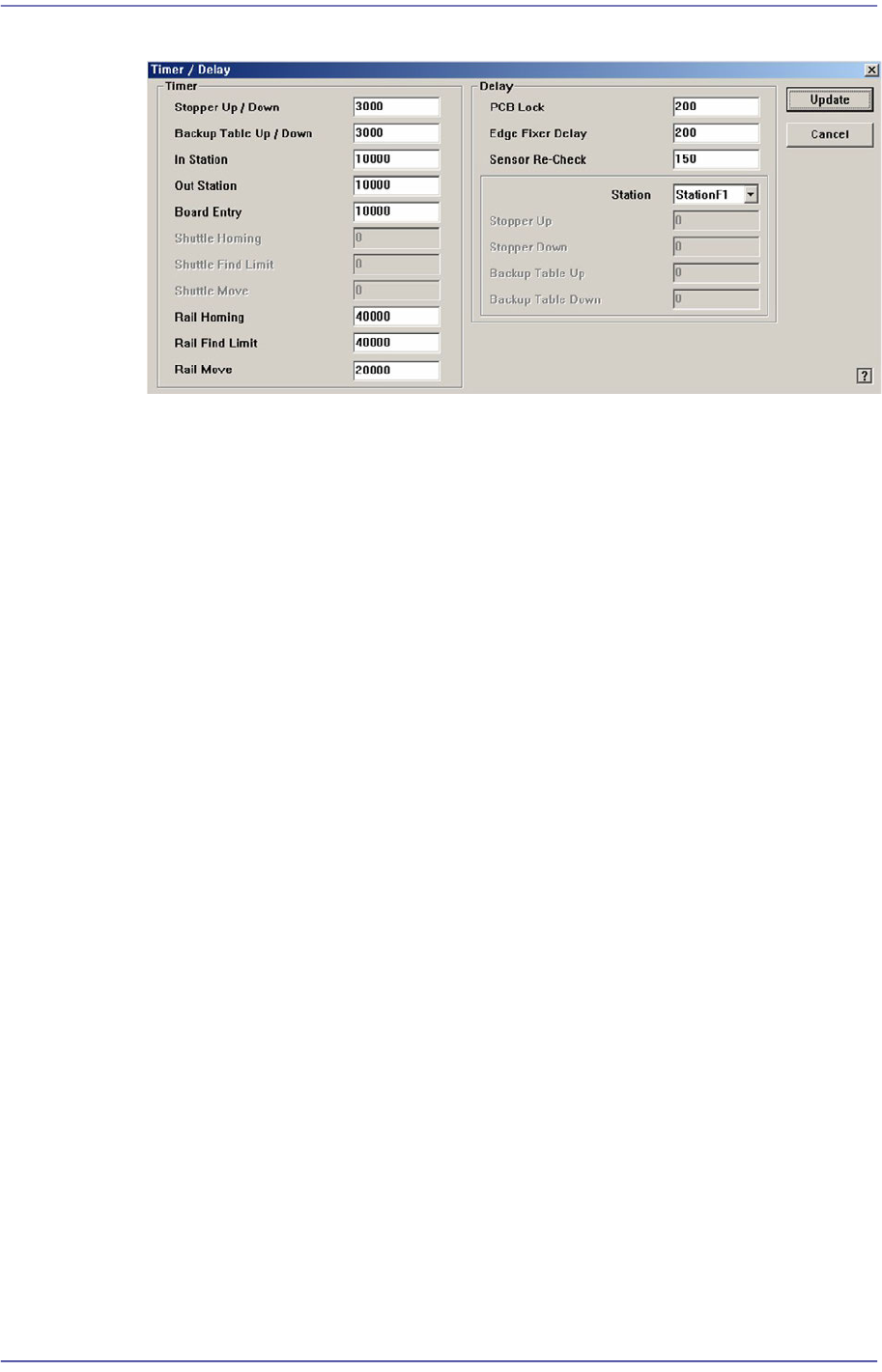
Figure15.4 “Timers/Delays” dialog box
<Timers> group
<Stopper Up / Down> edit box
If the Up/Down operation of the Stopper is not completed within the set time,
the machine will consider an error occurred during operation.
<Backup Table Up / Down> edit box
If the Up/Down operation of the Backup Table is not completed within the set
time, the machine will consider an error occurred during operation.
<In Station> edit box
If PCB-In operation is not completed within the set time, the machine will
assume an error occurred during operation.
<Out Station> edit box
If the PCB is not carried out within the set time, it is regarded by the machine
that an error occurred during operation.
<Board Entry> edit box
If the PCB is not transferred from the previous machine within the set period
of time, it is regarded by the machine that an error occurred during operation.
<Shuttle Homing> edit box
If the shuttle homing is not completed within the set period of time, it is
regarded by the machine that an error occurred during operation.
<Shuttle Find Limit> edit box
If the Shuttle Find Limit is not completed within the set period of time, it is
regarded by the machine that an error occurred during operation.
<Shuttle Move> edit box
If the Shuttle Move is not completed within the set period of time, it is
regarded by the machine that an error occurred during operation.

15-6
Fast Flexible Placer SM481(L) PLUS Administrator’s Guide
<Rail Homing> edit box
If the Rail Homing is not completed within the set period of time, it is
regarded by the machine that an error occurred during operation.
<Rail Find Limit> edit box
If the Rail Find Limit is not completed within the set period of time, it is
regarded by the machine that an error occurred during operation.
<Rail Move> edit box
If the Rail Move is not completed within the set period of time, it is regarded
by the machine that an error occurred during operation.
<Delays> group
<PCB Lock> edit box
The delay time until PCB Clamping is completed after sensing the Backup
Table Up sensor.
<Edge Fixer Delay> edit box
The delay time until PCB alignment is completed after the edge fixer is
operated.
<Sensor Re-Check> edit box
After the PCB detection sensor detects the PCB on the conveyor first, it
detects the PCB again after the lapse of time as long as the set delay time,
preventing the malfunction of the sensor.
<Station> combo box
Select the station for which the stopper related delay is to be set.
<Stopper Up> edit box
The delay time until PCB Clamping is completed after sensing the Stopper Up
sensor.
<Stopper Down> edit box
The delay time until PCB Clamping is completed after sensing the Stopper
Down sensor.
<Conveyor Rail Width Setting> button
Checks the current width of the placement station by recognizing the fiducial on the
conveyor rail when performing ‘Home’ ( ) for the equipment after booting it, and
compares this width with the saved width information before turning off the power
supply. It performs 'Home’ of the conveyor rail when there is a change.
Set whether to use the fiducial on the conveyor rail in order to perform ‘Home’
quickly for the placement station. This function is enabled in the SM411 model. (Dual
Lane Conveyor)