Hanwha SM481 PLUS Series Administrator’s Guide Eng.pdf.pdf - 第65页
3-1 File Shortcut Menu Chapter3. File Short cut Menu The <File shortcut> menu is composed of the following seven submenus: New , Open, Save, Save As, M er ge , Error MsgBar Show/Hide, Win d ows T ools , and Exit. F…

2-6
Fast Flexible Placer SM481(L) PLUS Administrator’s Guide
Jogbox
Checks the Teaching box function.
Tray
Checks the Tray Feeder function.
Motor IO
Indicates the status of sensor inputs related with each motor.
2.1.2.2.5. The submenu tool-bars of the Sys-setup menu tool-bar
Head
Calibrates the items related with the head.
Conv.
Sets up the items related with the conveyor.
Pos.
Sets up the items related with the feeder base and system dump box.
Camera
Sets up the items related with the camera and lighting.
Periph.
Perform setups related to the user defined dump box, tray feeder and peripheral
equipment.
Light
Executes light mapping.
Calib.
Perform complete calibration for the equipment.
Pref.
Sets various options necessary for equipment operation.
Device
Manages data related to the Tape, Stick, and Nozzle.
3-1
File Shortcut Menu
Chapter3. File Shortcut Menu
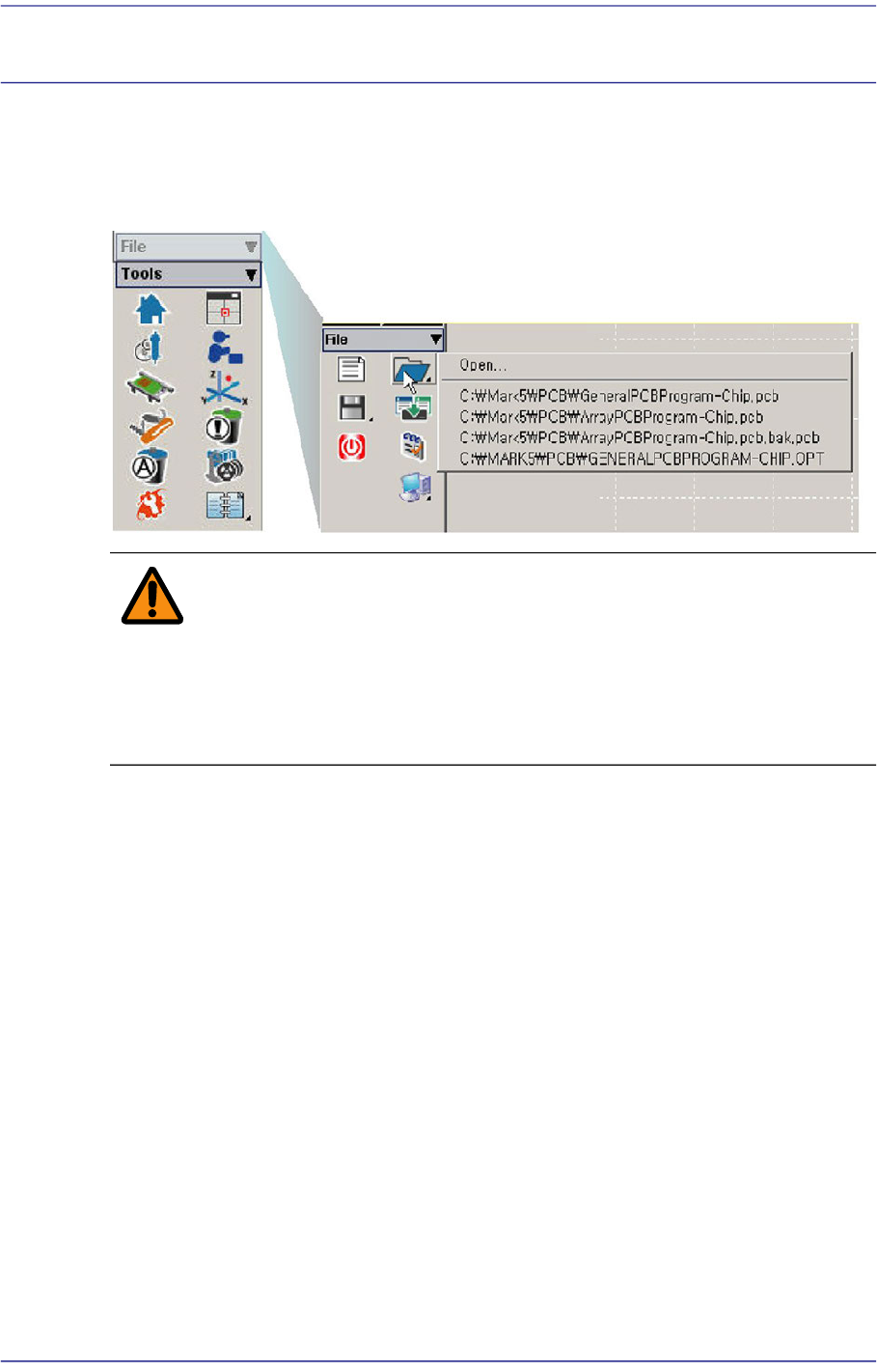
The <File shortcut> menu is composed of the following seven submenus: New, Open,
Save, Save As, Merge, Error MsgBar Show/Hide, Windows Tools, and Exit.
Figure3.1 File Menu and Submenus
Warning Except the PCB file, deleting or moving a system file or data
file arbitrarily could lead to the operation failure of MMI
program.
Except the PCB File, do not delete or remove a system file
or data file arbitrarily.
3-2
Fast Flexible Placer SM481(L) PLUS Administrator’s Guide
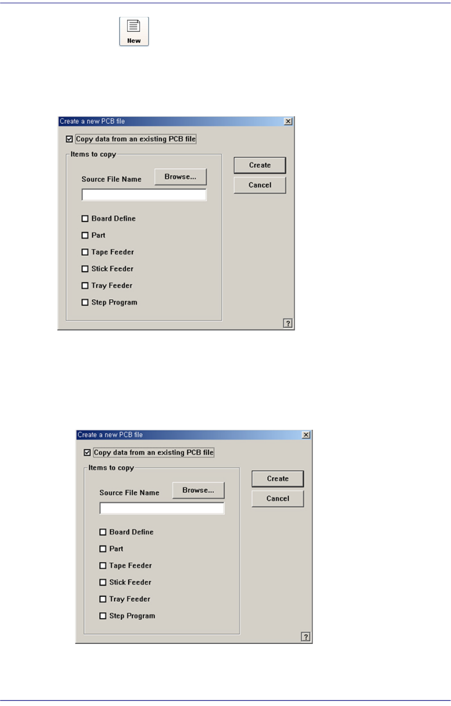
3.1. New [Ctrl+N]
<New> command is used to create a new PCB file. When the <New> command is
selected, the following dialog box is displayed.
Figure3.2 “New PCB File” dialog box
<Copy data from an existing PCB file> check box
Used to copy certain data from an existing file and create a new file. When this box is
not checked, default data is used to create a new file. When this box is clicked on, the
<Items to Copy> dialog box is displayed.
Figure3.3 “ Create a new PCB file” dialog box
<Browse...> button
Used to create a new PCB file from existing files. When this Button is clicked on,