Hanwha SM481 PLUS Series Administrator’s Guide Eng.pdf.pdf - 第255页
8-19 Feeder Setup 0: Not installed on any feeder base. 1: Installed on Feeder Base (Front Feeder Base) 1. 2: Installed on Feeder Base (Rear Feede r Base) 2. 2.<Slot No.> Displays the slot number of the feeder base …
8-18
Fast Flexible Placer SM481(L) PLUS Administrator’s Guide
box.
<Dump> column
When the stick feeder is installed in the corresponding slot, select the dump box
for the component placed on the stick feeder. Available dump boxes are as
follows.
System Dump: The dump box set in the system, it is installed in the front of the
conveyor.
User Dump: The dump box set in the system by the user, the location should be set
in the system..
<Unit> group
Select the feeder base unit to edit.
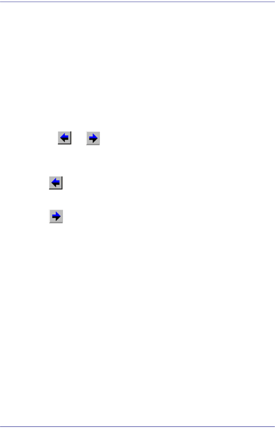
The and buttons are used for selecting the feeder base.
<Feeder Move> button
Moves the cursor only to the grid group where the feeder is installed.
button
Selects the slot previous to the slot of the currently selected stick feeder..
button
Selects the slot next to the slot of the currently selected stick feeder.
<Type> combo box
Select the type of stick unit to install. Available types are as follows.
Stack Stick: Stick unit where the same type of components are installed vertically.
Multi Stick: One or many types of components are installed horizontally.
Belt Multi Stick: Directly transfers the components supplied through the stick using
the motor driven belt conveyor.
Slim Stick: Composed of a structure that moves the stick forward and backward by
way of pneumatic pressure. The components are aligned on the component guide by
the impact caused from forward movement. They are then aligned with further
accuracy while slowly moving backward.
<Install to Feeder Base> group
When installing stick unit to the feeder base, set the feeder base unit and slot number
to install.
1.<Feeder Base>
Displays the feeder base where the corresponding stick unit is installed currently.
The numbers displayed are as follows.
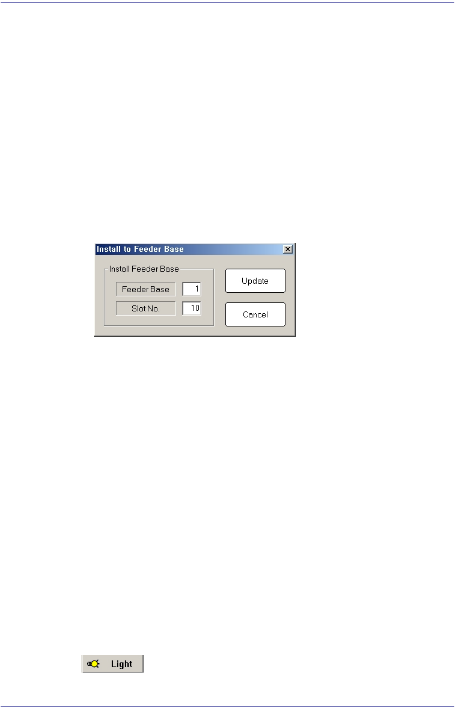
8-19
Feeder Setup
0: Not installed on any feeder base.
1: Installed on Feeder Base (Front Feeder Base) 1.
2: Installed on Feeder Base (Rear Feeder Base) 2.
2.<Slot No.>
Displays the slot number of the feeder base where the corresponding stick unit is
installed currently. The numbers displayed are as follows.
0: Not installed in any slot.
1 - 52: Installed in the corresponding number slot.
3.<Change…> button
In the case of installing stick unit to the feeder base, change the feeder base unit
and slot number to install. When this Button is clicked on, the following dialog
box is displayed.
<Install Feeder Base> group
Feeder Base
Displays the feeder base where the corresponding stick unit is installed
currently. The numbers displayed are as follows
0: Not installed on any feeder base.
1: Installed on Feeder Base(Front Feeder Base)1.
2: Installed on Feeder Base(Rear Feeder Base)2.
Slot No.
Designates the order in which the stick feeder is installed.
<Update> button
Saves the set contents and closes the dialog box.
<Cancel> button
Closes the dialog box without saving the set contents.
<Teach> group
Used for moving the selected object to the assigned position of coordinates by rotating
XY axis driving motor, or for obtaining the present coordinates of the selected object.
Button
8-20
Fast Flexible Placer SM481(L) PLUS Administrator’s Guide
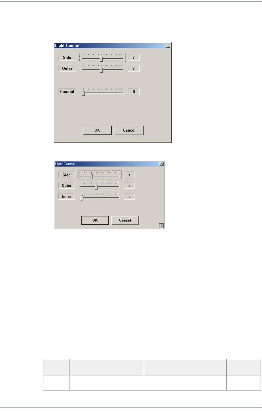
Setup illumination of fiducial camera to be used for teaching. When this Button is
clicked on, the following dialog box is displayed.
Figure8.8“Camera No. =Head Camera“ dialog box
Figure8.9“Camera No. =Fix Camera“ dialog box
<Side> slide bar
Set a value for the side light. (0 –15)
<Outer> slide bar
Set a value for the outer light. (0 - 15)
<Inner> slide bar
Set a value for the outer light. (0 - 15)
<OK> button
Saves the set light value and closes the dialog box.
<Cancel> button
Closes the dialog box without saving the set light value.
Table8.1Use of the Fix Camera Lighting
Light Use Applicable Part Remarks
Side Lights the edge of a part Chip, QFP, BGA, SOP etc