Hanwha SM481 PLUS Series Administrator’s Guide Eng.pdf.pdf - 第375页
14-23 Machine Calibration 14.3. Cali bration [F9] Only fix camera is activated. Used for setting up th e position of the f i ducial mark of the fix camera located at the upper part of ANC. The following are the works to …

14-22
Fast Flexible Placer SM481(L) PLUS Administrator’s Guide
combo box
Used for moving the selected object to the position of fix camera by rotating XY
axis driving motor, or for obtaining the present coordinates of the fiducial camera
Fid Cam: Selects fiducial camera.
<Move> button
Move the object selected in the combo box to the position of the assigned
coordinates. At this time, before executing <Move> button, the fix camera
corresponding to the desired position must be clicked on with a mouse.
<Get> button
Obtain coordinates for XY axis with reference to the object selected in the combo
box. At this time, before executing <Get> button, the fix camera corresponding to
the desired position must be clicked on with a mouse.
<Fiducial Mark …> button
Only fix camera is activated. Used for setting up the position of the fiducial mark of
the fix camera located at the upper part of ANC.
14-23
Machine Calibration
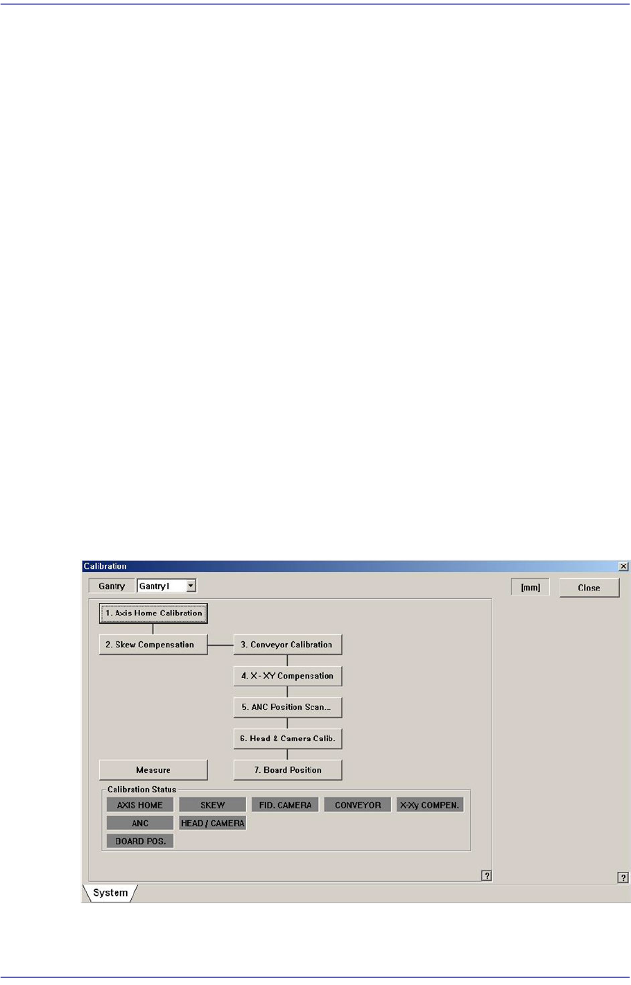
14.3. Calibration [F9]
Only fix camera is activated. Used for setting up the position of the fiducial mark of the fix
camera located at the upper part of ANC.
The following are the works to be performed before performing calibration or those to be
performed in advance.
I/O Test
Mirror offset check and correction
Nozzle check and vacuum check option for system constant
ANC type check
Pneumatic system check for any problem
The order in which the calibration is performed and the calibration tool needed to perform
the corresponding calibration is as follows;
Axis Home Calibration
Skew Compensation
Fiducial Camera Scale Calibration
Conveyor Calibration
X-XY Compensation – Calibration Bar
ANC Fiducial Mark Teaching
Head & Camera Calibration - CN040, CNT20, Light Fly Nozzle, Calibration Tool
14-24
Fast Flexible Placer SM481(L) PLUS Administrator’s Guide
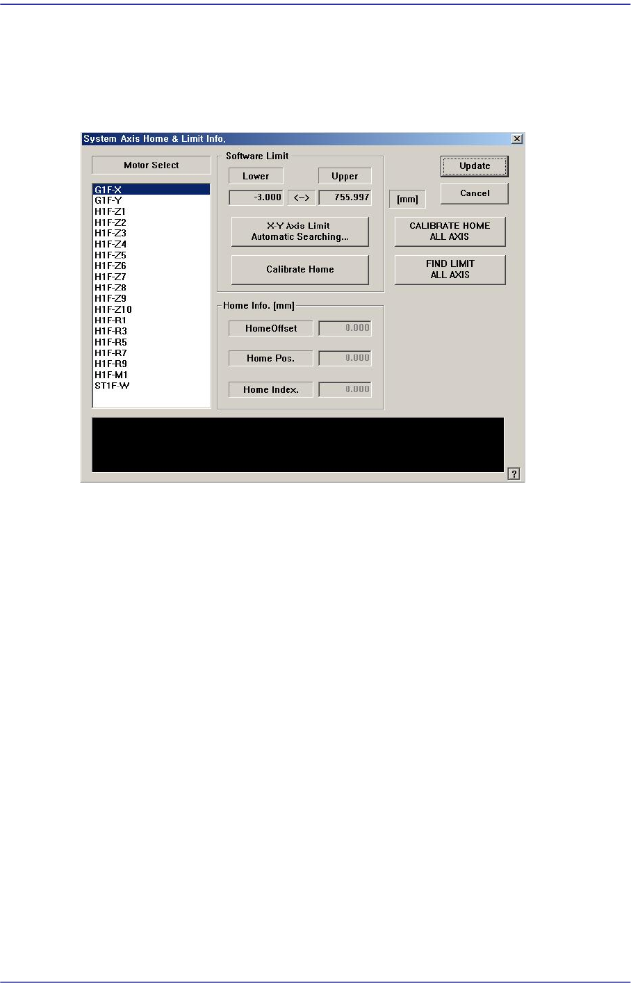
14.3.1. Axis Home Calibration
Sets the limit position of each axis to move. When this button is clicked on, the following
dialog box is displayed.
Figure14.8 “System Axis Limit Info.” dialog box
<Motor Select> list box
Select the motor axis for which to set the limit. Available axes are as follows.
G1F-X: X axis of the front gantry
G1F-Y: Y axis of the front gantry
H1F-Z1: Z axis of head1 of the front gantry
H1F-Z2: Z axis of head2 of the front gantry
H1F-Z3: Z axis of head3 of the front gantry
H1F-Z4: Z axis of head4 of the front gantry
H1F-Z5: Z axis of head5 of the front gantry
H1F-Z6: Z axis of head6 of the front gantry
H1F-Z7: Z axis of head7 of the front gantry
H1F-Z8: Z axis of head8 of the front gantry
H1F-Z9: Z axis of head9 of the front gantry
H1F-Z10: Z axis of head10 of the front gantry
H1F-M1: Mirror axis of the front gantry
H1F-R1: Theta axis (H1, H2) of the front gantry
H1F-R3: Theta axis (H3, H4) of the front gantry